Small scale passenger hauling Petrol-Electric / Diesel-Electric Locomotives in 5 and 71/4 inch gauge generate power at low voltage, 24V and 48V systems being typical.
Vehicle alternators or other a.c. generators are often employed, the a.c. being converted to d.c. before feeding to the motor control system.
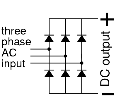
Single phase rectifiers use 4 diodes in a bridge configuration, three phase bridges use 6 diodes. In either case, no more than two diodes will be conducting at any instant, and each will have a voltage-drop across it of around 1 to 1.6 volts
As an example, if the combined voltage drop across the two conducting diodes is 2.4v, and the system is designed as a 24v system, 10% of the generated voltage is lost in the rectifiers.
As the current in the diodes is the load current, this means that 10% of the power is wasted as heat in the rectifiers. With a load current of say 30A, this wastes 2.4 x 30 = 72 Watts, requiring significant heat-sink hardware, blower fans, or both. Vehicle alternators have the rectifiers built in with a fan, cooling the whole.
The idea of synchronous rectification is not new, but the latest in MOSFET technology makes implementation both simple and affordable. The idea is simple - most of the forward conduction loss associated with diode rectifiers can be saved using MOSFETs as power switches turned on and off as needed. For example, using MOSFETs with a 0.004 Ohm 'on' resistance, the load current flows through a total resistance of 0.008 Ohm. At 30 Amp load current, the power loss will be 30 x 30 x 0.008 = 7.2 Watt
Power Loss Saving = 90% !
The same technology can be applied to extend battery life in battery powered locos as well. Typically motors are controlled using switching electronics employing 'pulse width modulation' (PWM) or similar techniques, where motor current flows alternately between the supply (during 'on' times) and a catch diode (during off times). Catch doide losses can also be reduced using synchronous rectifiers.
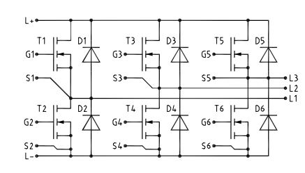
The MTI 85W100GC is a 100V 120A three-phase full bridge mosfet module with quoted 'on' resistance of 0.0032 Ohm per mosfet.
Each mosfet can be driven by a Synchronous Rectifier Controller, NCP43080 is a good choice.
Diodes D1 to D6 shown in the 3 Phase MOSFET diagram are inherent 'body diodes' of the mosfets - the 3 phase mosfet bridge could be used as a conventional rectifier with no additional parts. However, synchronous rectifier controllers can be used to switch a mosfet on whenever current flow is in the direction of diode conduction, effectively bypassing the diode and avoiding most of the power loss.
The 3 phase mosfet bridge is the near-ideal power-electronics module to drive 3 phase a.c. motors such as brushless (so-called Brushless D.C.) motors, the inbuilt body diodes being used as catch diodes for pwm or similar. The same 3 phase mosfet module could be used to synchronously rectify currents otherwise flowing through the body diodes with the associated loss. However, complicating the mosfet drivers may not be desirable, but using two mosfet modules in parallel works well.