If you have ever watched a 3D Printer or other Computer Numerically Controlled - CNC - machine at work and wondered how all the complex movements are coordinated, here's the explanation.
We'll talk about a machine that makes or modifies three dimensional objects by moving a tool relative to the work piece in the conventional '3D space', using a controlled motor to move each of the X, Y and Z axes. This could be a 3D printer, milling machine etc.
The motors moving the machine axes will each be driven by some axis motor controller. The computer will provide two binary signals to each axis motor controller, a 'Step' signl and a 'Direction' signal. Each pulse of the 'Step' signal will cause an axis move by some tiny distance in the direction determined by the '1' or '0' signal applied to 'Direction'. Axes can be set to move at any practical speed by choosing a rate at which 'Step' signals are sent. NCOs, one per axis, are used to generate the Step and Direction signals. The control computer updates the NCOs thousands of times per second giving the impression of movement in circles, spirals or along any complex path. In reality the machine is capable only of movement in straight lines in any direction through the XYZ space. By updating the path direction fast enough we can cause the machine to move along any desired path within close tolerances.
A NCO has a number passed to it from the control computer. This number determines the NCO output frequency, the number of 'STEP' pulses produced per time, which will remain constant until the control computer updates the NCO with a new numeric value. Thus the NCO when used to generate signals for any axis motor drive, determines the velocity of the axis, and not the position along that axis.
By using Numerically Controlled Oscillators, one for each axis under control, the computer is given a simple method to set a number of axes moving at well defined velocities - important to note - the velocities are under control and not the position. To go to a new position the computer will have worked out for what time which axes should move at what velocities.
Like most of the parts that go to make up computers and CNC machines, the NCO comes from a very simple idea - it's about counters going 'round the clock' as we used to say when car odometers only went up to 99,999 miles, then back to 00,000. The technical term for this is 'Overflow'.
Computers, however, do not organise counters in this way. Computers work in binary, using binary 'bits' ('bit' = Binary digIT) instead of decimal 'digits'. Each binary 'bit' may contain only a '0' or a '1'. If we had a 3 bit binary counter, it could count up from 000 to a maximum of 111.
This example can hold any value from zero (000) to seven (111) - not too useful, but every time you increase the size of counter by adding one more 'bit' you double the range - a four bit counter goes up to 15, a five bit to 31, a six bit to 63...
The MSB and LSB labels indicate the 'Most' and 'Least' Significant Bits (by convention the LSB is labelled Bit0, and in the case of a 3 bit counter the MSB will be Bit2). By the time you've got up to the 32 bits used even in older computers, the maximum number is over four billion - enough for our purposes!
Using the simple example of a binary counter with 3 'bits', the number it contains counts up by one each time it gets a 'clock' pulse. The computer supplies clock pulses at some fixed frequency of, say, 'f' clock pulses per second. It will 'count' up in the above sequence.
The signal 'Bit2' (MSB) repeats on every eighth clock pulse - producing a signal of frequency (f / 8) at the MSB.
Each time the state of the MSB changes from '1' to '0', this indicates an 'Overflow' has occurred, we've gone 'round the clock'.
If the counter counted down instead of up, the counter would 'Underflow' at the same rate, the effect is the same.
Considering clock frequency 'f'. This is a fixed speed, or frequency, the one that Mach3 CNC software calls "Kernel Speed". In Mach3 this may be something like 25,000 cycles per second, 25kHz.
There is advantage to be gained by making this 'speed' as fast as is reasonably achievable. This speed (25kHZ) is often about as fast as safely deliverable using software implemented NCOs as with Mach3 running on a PC.
NCOs implemented in hardware (using gate arrays in external motion controllers, for example) can work very much quicker.
Looking at the general case of output frequency 'f' when the counter is clocked at Kernel frequency 'K' and incremented by any number 'N' on each clock
  Adding N = 0 on each clock
	0 0 0    (0)
	0 0 0    (0)
	0 0 0    (0)
	0 0 0    (0) etc
	0 0 0    (0) repeats
  Output frequency f = 0

  Adding N = 1 on each clock
	0 0 0    (0)
	0 0 1    (1)
	0 1 0    (2)
	0 1 1    (3)
	1 0 0    (4)
	1 0 1    (5)
	1 1 0    (6)
	1 1 1    (7)
	0 0 0    (0) overflow
  Output frequency f = K / 8

  Adding N = 2 on each clock
	0 0 0    (0)
	0 1 0    (2)
	1 0 0    (4)
	1 1 0    (6) overflow
	0 0 0    (0) repeats
  Output frequency f = 2K / 8

  Adding N = 3 on each clock
	0 0 0    (0)
	0 1 1    (3)
	1 1 0    (6)
	0 0 1    (1) overflow
	1 0 0    (4)
	1 1 1    (7)
	0 1 0    (2) overflow
	1 0 1    (5)
	0 0 0    (0) repeats
  Output frequency f = 3K / 8

  Adding N = 4 on each clock
	0 0 0    (0)
	1 0 0    (1)
	0 0 0    (0) overflow
	1 0 0    (1)
	0 0 0    (0) overflow
	1 0 0    (1) repeating
  Output frequency f = 4K / 8
Possible output frequencies cover a range from zero to half 'Kernel' frequency (google Nyquist, Shannon, sampling theorem ffi).
The factor '8', common to above shown examples is 2 to the power of 3 (23).
In general, for a counter size of 'm' bits, the factor is 2m
Generalised NCO output frequency formula :-
f = N * K / 2m
By making the number of bits 'm' = 32, using 32 bit arithmetic available with most modern controllers, we can generate over 2 billion discrete frequencies.
By arranging to use numbers in the high millions, there will always be a 'close enough' number.
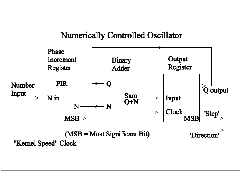
Here is a schematic of a practical Numerically Controlled Oscillator. It may be implemented in hardware or software.
Numerically Controlled Oscillator
The NCO consists of two registers (places where 32 bit binary numbers may be stored and modified) and one adder capable of adding 32 bit binary numbers.
The 'Phase Increment Register' (PIR) holds a number 'N' sent from the computer, this number is presented to one input of the binary adder.
The 'Output Register', (otherwise known as the 'accumulator') stores a copy of the adder output at the instant it sees a clock edge on the 'Kernel Speed' clock input. This output is fed back to one input of the adder, where this new Output Register value is added to the number 'N' in the PIR. The result of this addition will be available some short time later and will be complete and settled in plenty of time for the next clock edge at 'Kernel Speed'. The Output Register may be thought of as a 'running sub-totaller' which will 'Overflow' at a rate proportional to 'N'.
The output frequency Fout = 'Kernel Speed' * N / (2 to the power of 32)
Forward, Reverse and Stopped
If the number 'N' in the PIR is positive, the 'count' counts up. If negative, the count counts down. Setting 'N' to zero stops the axis.
As we have seen, the most significant bit (MSB) of the Output Register may be used directly as the stepper motor controller 'STEP' signal.
Using the two's complement format for 'N', when N is negative the MSB or left-most bit will be '1', and for zero and all positive N values it will be '0'.
To summarise, the PIR MSB provides the 'DIR' signal, and the Output Register MSB provides the 'STEP' signal.
Software Implementation
The diagram above shows how to implement the NCO in hardware using a gate array or similar, but software implementation is quite straightforward.
The computer will need to give access to a timer capable of generating interrupts, the timer will need setting up to generate interrupts at 'Kernel Speed'.
The work of the NCO is then performed in the 'Interrupt Service Routine' (ISR), a sketch of one possible implementation is shown below, this was
run on the ARM Cortex M3 processor (see mbed.org). Note this also updates three global 'DRO' registers for use elsewhere in the code giving positional data.
/*
*   Interrupt Service Routine
*/
void    Numerically_Controlled_Oscillators_ISR ()  {   // services Ticker 'NCO_gen' generated interrupts ***ISR***
    const   int     bits2shift = (sizeof (long) << 3) - 2;
    const   int     bit_lutx[4] = {0, 2, 3, 1};  //  Used to look-up 'clk' and 'dir' signals from accum MSBs
    const   int     bit_luty[4] = {0, 8, 12, 4};  //  Used to look-up 'clk' and 'dir' signals from accum MSBs
    const   int     bit_lutz[4] = {0, 32, 48, 16};  //  Used to look-up 'clk' and 'dir' signals from accum MSBs
    static  unsigned long
        acc_x = 0L,		//	Output registers for three axes
        acc_y = 0L,
        acc_z = 0L;
    static  int obitz = 0;
    int oldbitz, acts;

    intled = 1;     //  LED on for duration of interrupt service - point for scope probing
    ticks++;        //  count of interrupts serviced
    acc_x += pir_x;     //  Update phase of signals in accumulators
    acc_y += pir_y;
    acc_z += pir_z;
    oldbitz = obitz;    //  pin output levels as determined during previous interrupt
    obitz = bit_lutx[acc_x >> bits2shift] | bit_luty[acc_y >> bits2shift] | bit_lutz[acc_z >> bits2shift];
    mysteppers = obitz; //  Output signals to stepper motor drivers, next look for _- pos clk events on bits 0, 2 and 4
    acts = (~oldbitz & obitz);  //  get pos clk edge triggers in bits 0, 2 and 4 (1, 4, 16)
    acts |= (obitz & 0x2a);      //  get directions in bits 1, 3 and 5 (2, 8, 32)
    if(acts & 1)    {           //  got pos clk edge for axis X
        if  (acts & 2)
            dro.x++;
        else    dro.x--;
    }
    if(acts & 4)    {           //  got pos clk edge for axis Y
        if  (acts & 8)
            dro.y++;
        else    dro.y--;
    }
    if(acts & 16)   {           //  got pos clk edge for axis Z
        if  (acts & 32)
            dro.z++;
        else    dro.z--;
    }
    if  (running && tickrun <= ticks)   {   //  End of a machine movement detected, start next move here if possible
        running = false;
        pir_x = 0L; //  stop all stepper motors
        pir_y = 0L;
        pir_z = 0L;
    }
    intled = 0;         //  LED off
}           //  end of interrupt handler
/*
*   End of Interrupt Service Routine
*/
June 2014 - the above was an early code version. All the latest code is available for you to see, copy and use and may be found on the mbed web site, a search for 'Jon Freeman CNC' should find what you're looking for.