The story of my meandering into model engineering may be familiar to many. From an early age I was fascinated by clocks, steam locomotives, anything mechanical. While still at school I decided to start building a miniature loco, and with some help from kindly members of a local model engineering club and the metalwork teacher at school, a start was made on a simple 0-4-0, 'Juliet'. I acquired my first lathe, a small lathe, popular at the time. The following forty years saw very little progress, the time being occupied with a career in industry, paying mortgages, and all the predictable distractions of an ordinary life.
With the prospect of retirement and some free time at last, I signed up for some spare-time voluntary work in the locomotive restoration department of a nearby heritage railway. I was soon let loose machining items for full-size locos in steel, brass and bronze using a variety of ancient industrial machines, lathes much bigger and heavier than the small lathe I was accustomed to.
I dusted off the home lathe and made a few more parts for Juliet. I quickly learned that although the small lathe was adequate for making very tiny items, for even quite small parts it was often quicker and easier to use a larger lathe. Whereas at home I could just about tickle 0.020 inch (or 0.5mm) off the diameter of a short piece of one inch steel before the chatter set in or the spindle stalled, I could remove ten times as much per cut on a heavy lathe, using tipped tools and running at much higher RPM. Some tasks could be completed in minutes on a big lathe that would have taken hours on the small lathe! Clearly I needed a bigger lathe for my home workshop, keeping the small lathe for the small stuff …
I can be impetuous, as I was on the day I set off to visit Chester Machine Tools. Although I had not done any research beforehand, using my new experience with bigger lathes I had in mind some essential minimum requirements:-
Big, heavy, solid and stiff
Digital readout (DRO)
Power feed to saddle and cross slide
Quick change tool post
Good range of metric and imperial screw cutting options
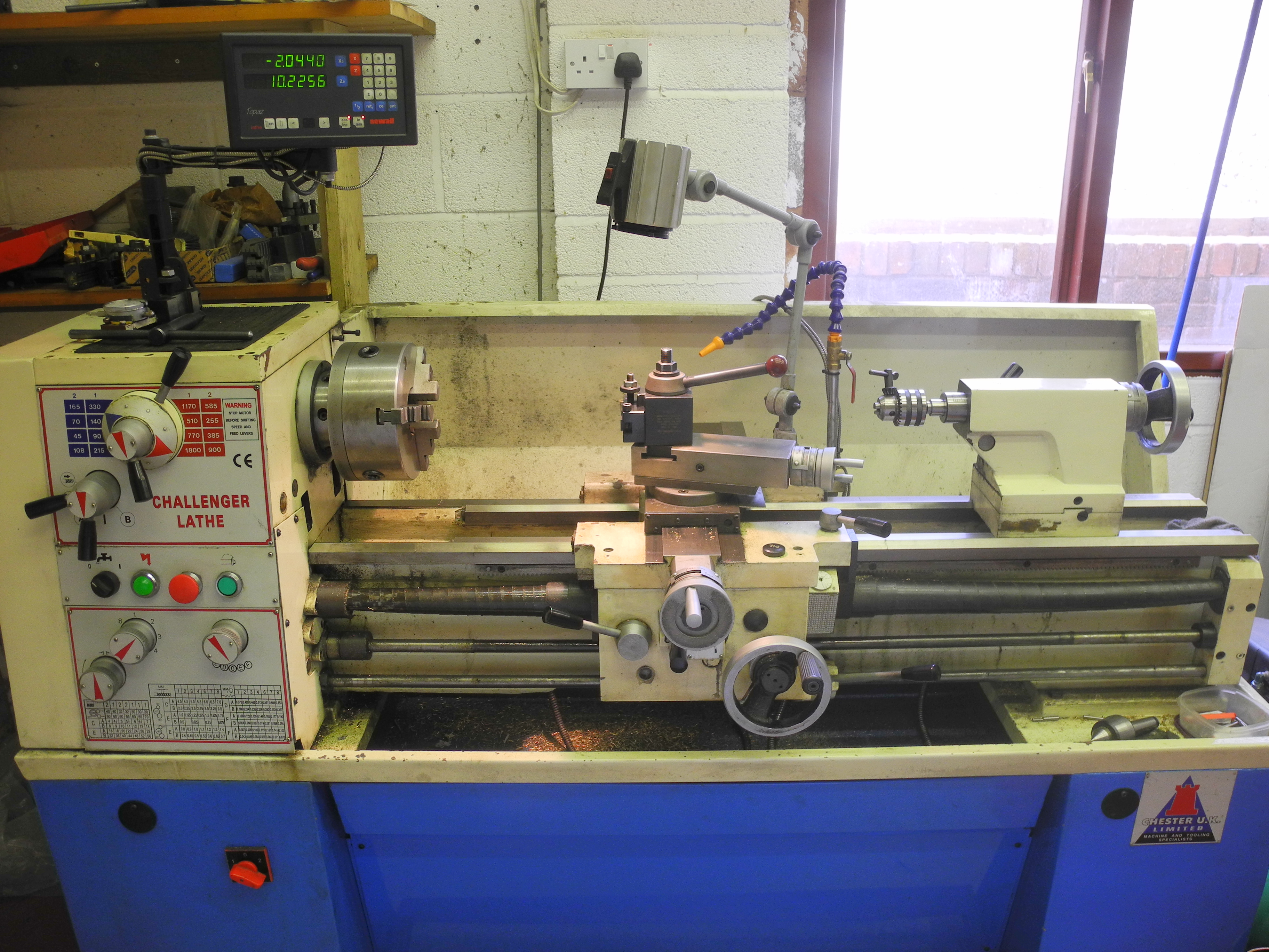
I also had some thoughts on what I did not want. Having acquired a small mill-drill, I no longer wasted time messing about with swivelling vertical slides or any other bolt-ons to press the little lathe into use for milling or any other tasks for which it was not designed. I was looking for a straightforward, no nonsense lathe. I departed Chester having placed an order for the “Challenger”, a 16 speed, geared head, 750kg heavyweight, the identical (or almost so) available from a number of suppliers as type “GH1440”.
The lathe was delivered, hoisted onto the drive outside. Moving it into the workshop and into position was quite a pantomime involving all available local muscle, a fork lift, engine hoist and anything handy and round for use as rollers. I should have thought this through beforehand, but the lathe needed levelling as the concrete floor was anything but. My solution was to make a set of six screw adjusters, one for each of the holes provided for bolting down the lathe, four at the headstock end and two below the tailstock. Using a spirit level, the machine was quickly levelled by adjusting the six screws. As the final part of setting up, a long, stout, brass bar was chucked in the three jaw and a very light cut taken along the length using a freshly sharpened HSS tool. The diameter measured at each end was then compared and any difference noted. If more than a thousandth of an inch or so, the leveller at the tailstock end was adjusted as the difference evidenced a minute degree of twist in the bed. This process was repeated until no error was measurable.
After twelve years with the Challenger, time to review how well it has lived up to my original requirements:
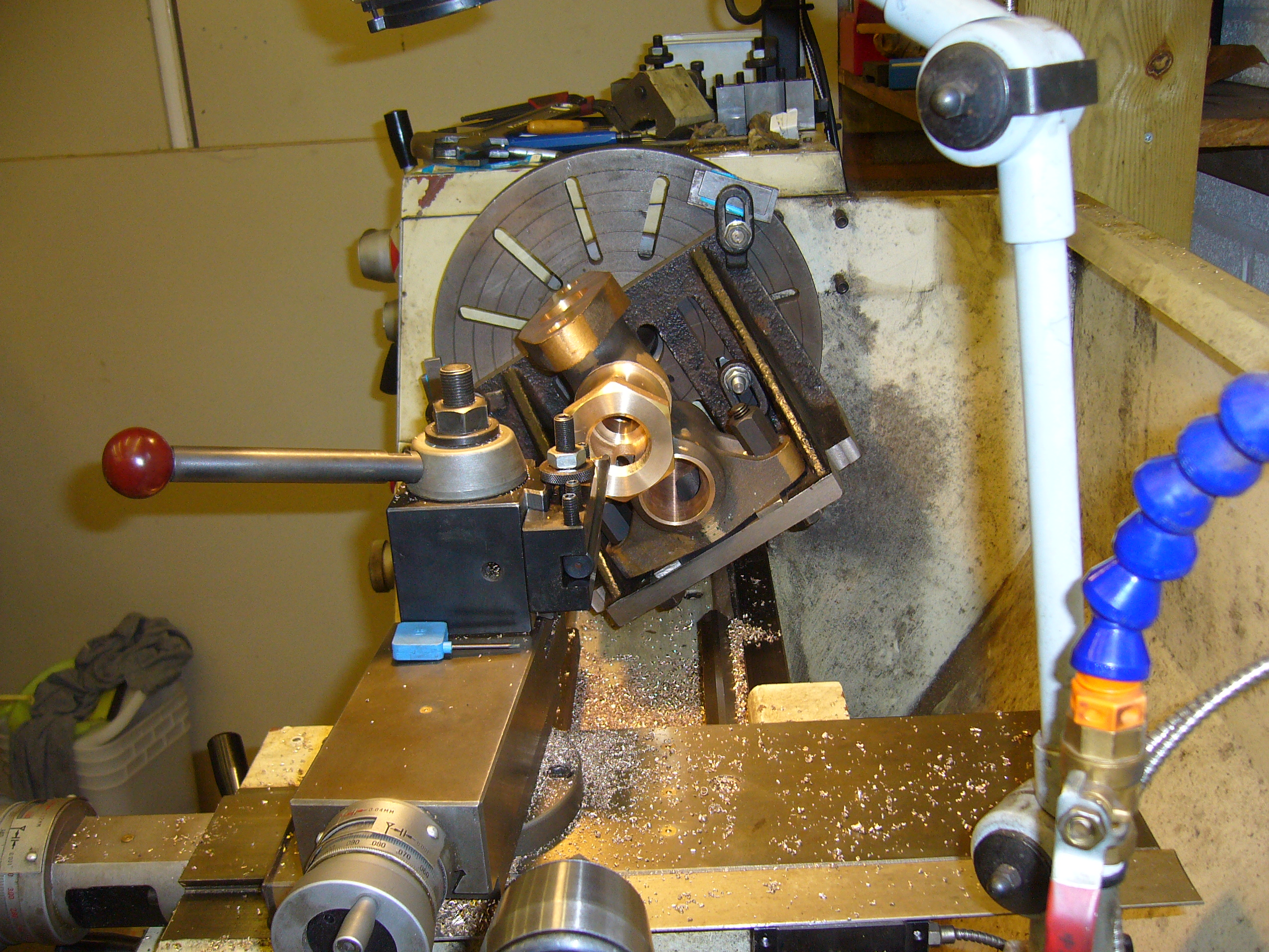
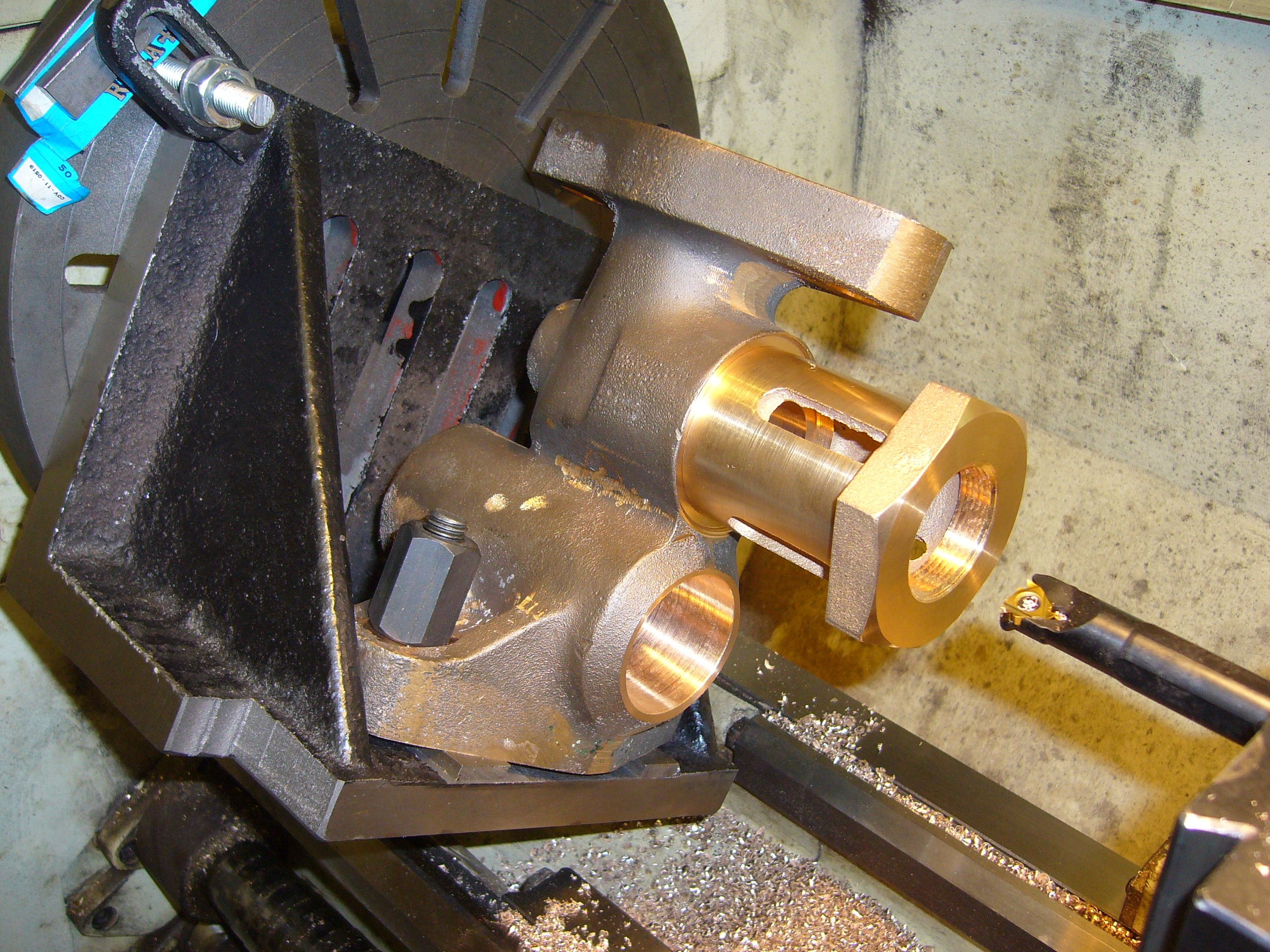
I've used the Challenger to produce parts both great and small. I've worked on locos ranging from 5” up to “standard” gauge, machined parts for agricultural machines, and once machined a steam truck flywheel, so heavy I could barely lift it. Beyond straightforward turning, I've had the occasional interesting job such as the steam valve fitting shown in figures 2 and 3. This was for a standard gauge GWR loco, and involved mounting a large casting on the faceplate in various positions and orientations prior to facing, parallel and taper turning, and screw cutting.
In all this time I've never needed or even wanted a bigger lathe. The large 3-jaw chuck will not hold anything smaller in diameter than about 4mm, but for the smallest stuff I grip a smaller 3-jaw chuck in the large one, that does the trick. For large work, with a tipped tool I can easily rip 5mm or 3/16” from the diameter of a 3” steel round turning at 585 RPM with an aggressive feed-rate, so long as I keep an eye out for any fires started around the workshop by hot, flying swarf! With a lathe weighing three quarters of a ton, I'm glad to say I've never managed to make the machine shake, rock or complain in any way. Oh yes, I did once destroy a fairly expensive parting tool, but this taught me not to try any ambitious parting operations on steel without flooding with cooling, lubricating suds.
The DRO (seen in Fig 1) makes working so much quicker and easier, also helping avoid mistakes. It is also useful being able to flip between metric and imperial readout at the touch of a button – no more cursing the lead screws and graduated dials for being in the “wrong” units. The Newall DRO fitted to my lathe stores positional information for a number of tools. This, along with the quick change tool post, enables rapid tool change without having to re-establish datum at each change – a great aid to speedy and efficient working, particularly with batch or any repetitive work.
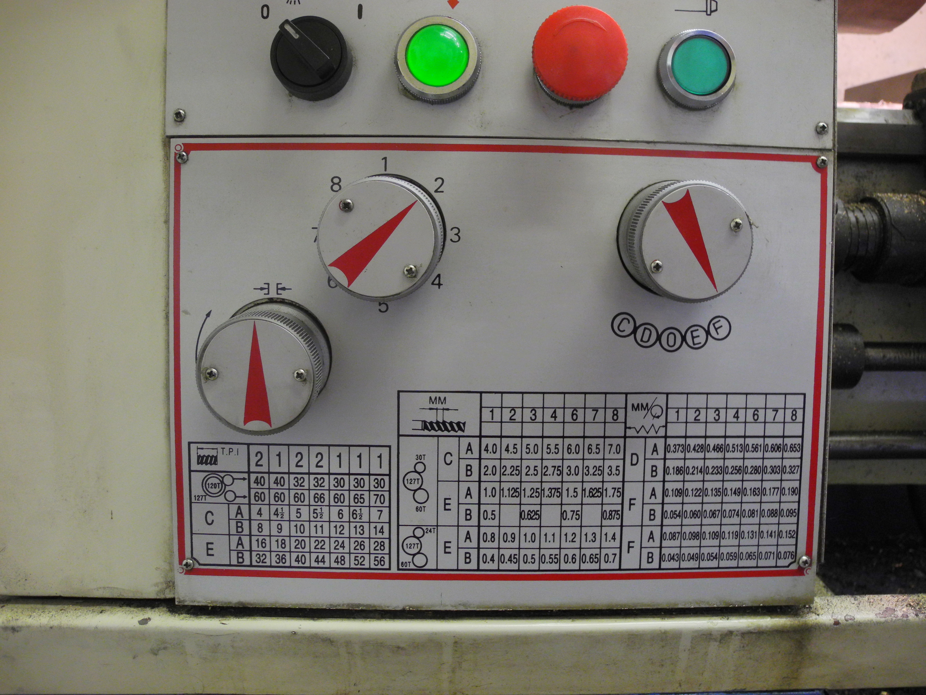
Fig 04 - Challenger Lathe Thread Chart Plate and Controls
When it comes to screw cutting, I do remember at Chester, dismissing one of the smaller lathes because the screw cutting chart attached did not include 26 TPI threads, a known favourite. I did not notice at the time that the Challenger, a metric lathe by design, although showing how to set for many useful imperial threads, did not include 19 TPI in its chart, a need I would subsequently discover.
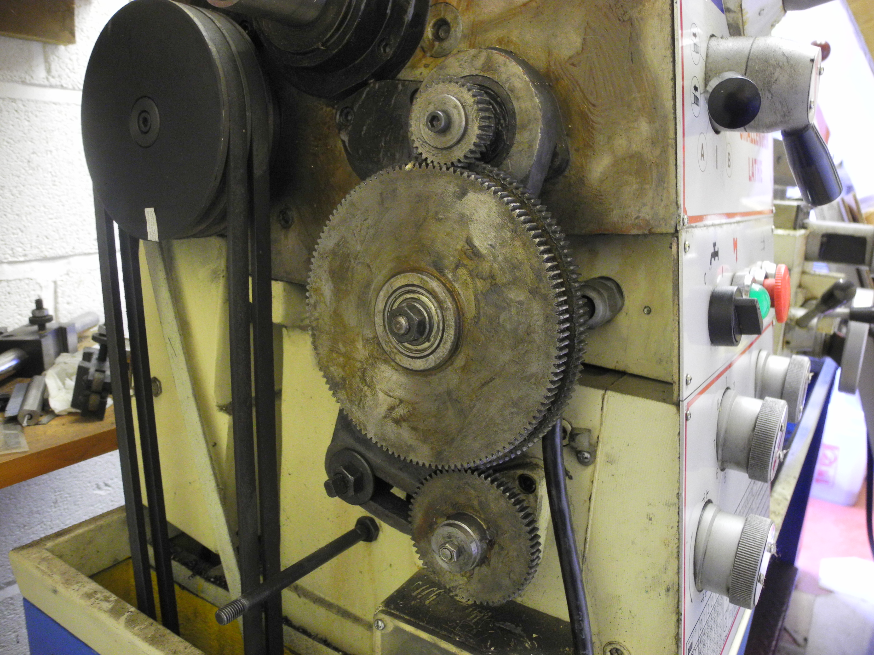
Fig 05 - Greasy Lathe Change Wheels
To set up for screw cutting on many lathes including the Challenger, requires selecting and fitting a pair or set of change-wheels, and setting some knobs, handles and levers to the positions indicated on the screw cutting chart affixed to the lathe (Fig 4). Changing the wheels is a bore, not difficult, just tedious, messy and time consuming (Fig 5). I noticed from the chart however, there are many possible combinations of change wheels, knob and lever position settings, which are not listed in the chart (and this applies to many other lathes). This observation led me to create an Excel spreadsheet on the computer to show all the screw cutting possibilities for all of the 2048 possible ways of setting up the Challenger, in both metric and imperial – rather more than the 28 imperial and 39 metric options shown on the chart. Fig 6 shows a screen shot. From this I found three different ways of setting the machine to cut 19.05 TPI threads. Although not exactly 19 TPI, this was close enough – strictly a metric pitch of one and a third milli-metre.
The spreadsheet also revealed several ways of setting for many frequently used threads, sometimes meaning no mucky wheel changing was needed, just setting the knobs and levers to positions revealed by the spreadsheet, rather than the chart!
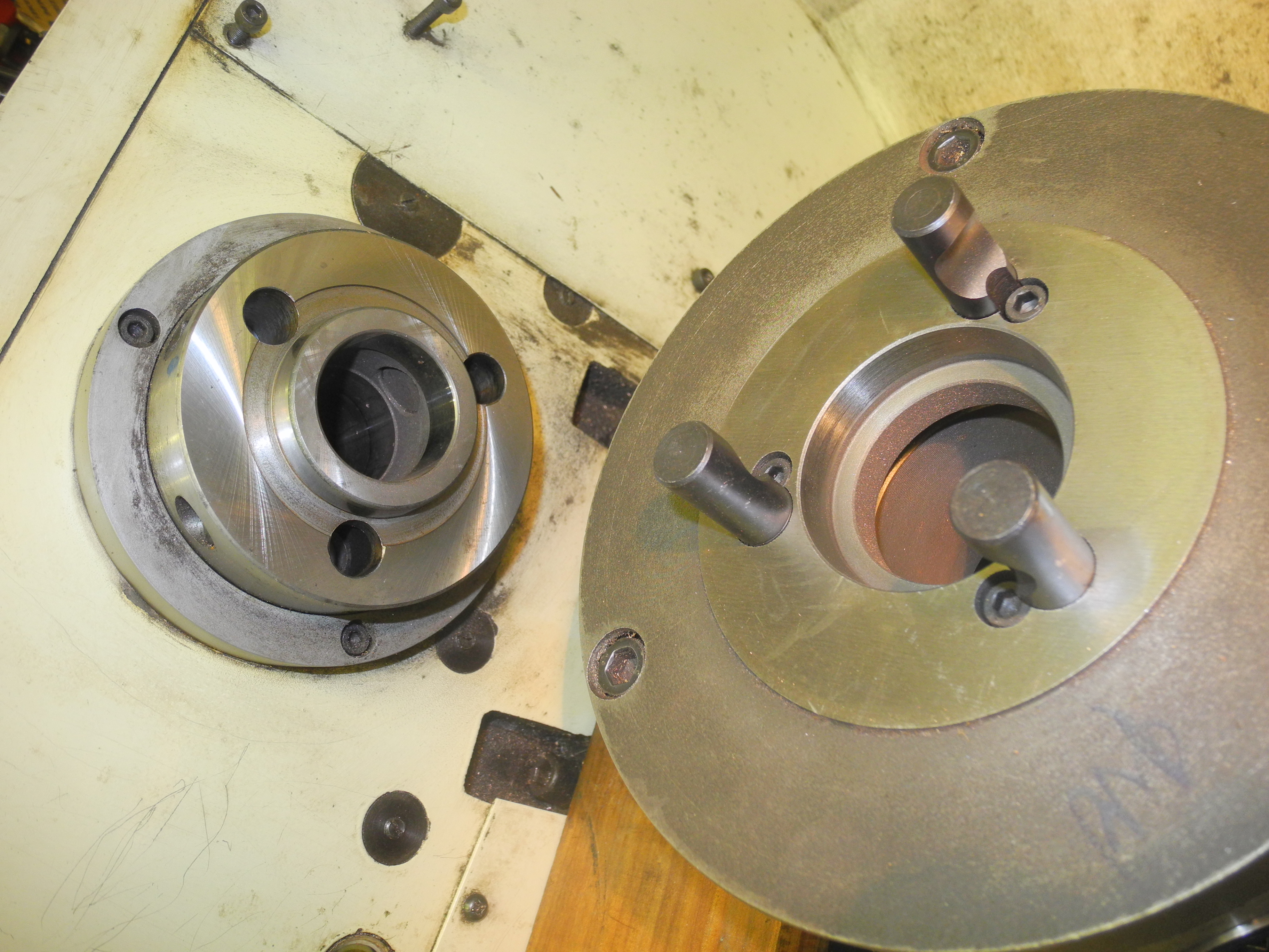
Fig 07 - Camlock chuck removed
One thing not on my list of original requirements, that would have been if I'd known then what I know now - Camlock spindle nose fitting. The Challenger has Camlock D1-4, and it is excellent.
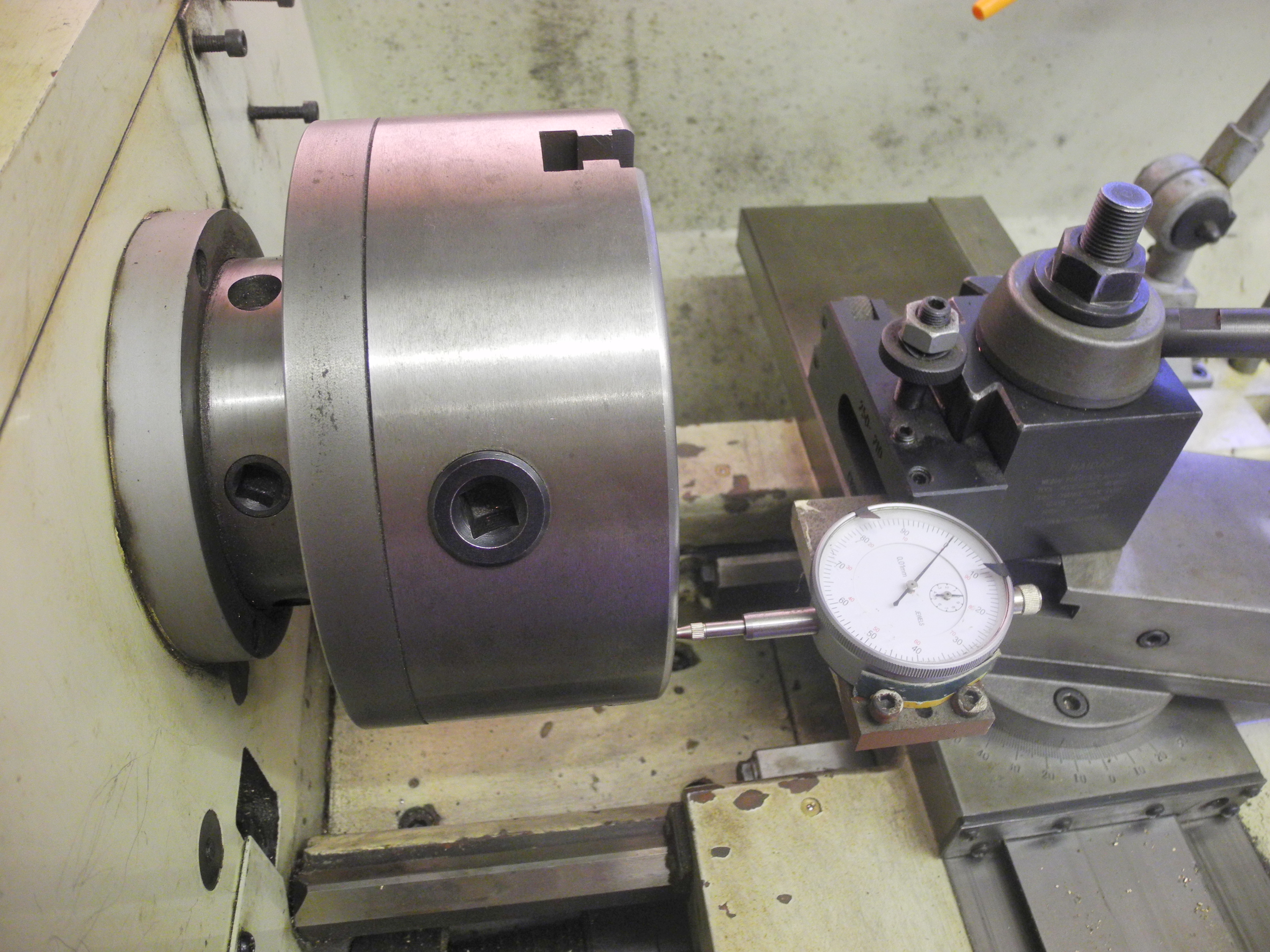
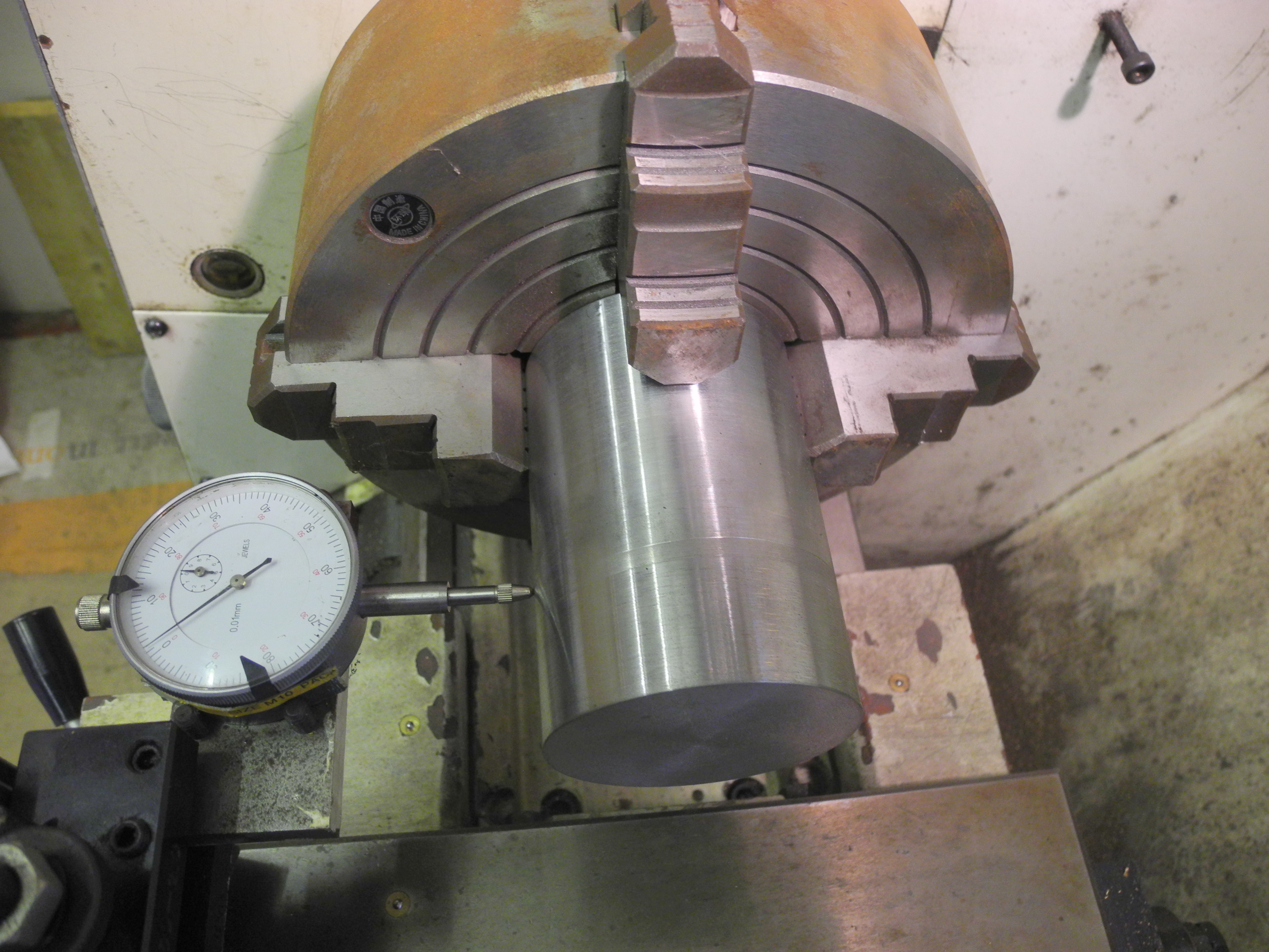
Fig 08 - Setting Chuck to run true
My small lathe had a threaded spindle nose. After carefully cleaning muck and swarf from the threads, a faceplate or chuck would be screwed onto the spindle nose. This is all well and good, but precludes any serious use running the lathe in reverse for fear of the chuck unscrewing. If the chuck runs true enough then good, but what to do if it runs out? Camlock addresses these problems. First, you can run the lathe in either direction with confidence. Those of a nervous disposition might prefer to cut threads in reverse such that the tool rushes away from the chuck instead of towards it – one of many good reasons perhaps. The other huge benefit of Camlock is that it provides for minute adjustment to get the chuck running as true as you can be bothered to set it. Fig 7 shows the chuck removed from the spindle. The Camlock chuck is held in position, pulled hard onto a precision ground cone by cams interlocking with curved recesses in three pins, shown in fig 7. When fitting a chuck, the trick is to offer it up into position and then turn the three cams to just pinch gently. Fig 8 illustrates my preferred method for adjusting and testing for true running. The cams have a square hollow to take a chuck key, one visible to the left of the chuck in Fig 8. The DTI is brought up to make contact with the face of the chuck with jaws removed, the spindle is turned by hand, each cam in turn is gradually tightened, a little at a time, while noting the effect on the DTI reading. With the DTI bearing close to the outer edge, a couple of minutes spent going around selectively and progressively tightening the cams should be enough to pull the chuck into 'true', all but eliminating any measurable run-out of the chuck face. This becomes easier with practice. What this method does is to set the axis of the chuck to be in-line with the spindle axis. With my 3-jaw self-centring chuck, this also means a piece of round can be chucked and expected to run 'true' within about five thousandths of an inch – quite good enough for most purposes. Where the ultimate in true-running accuracy is required I use the 4-jaw, adjusted onto the Camlock as described above, and then the work centred with aid of the DTI setup shown in Fig 9. Again, this only takes a couple of minutes – turned by hand while adjusting tightness of each jaw to get job centred as witnessed by DTI – gets easier with practice.
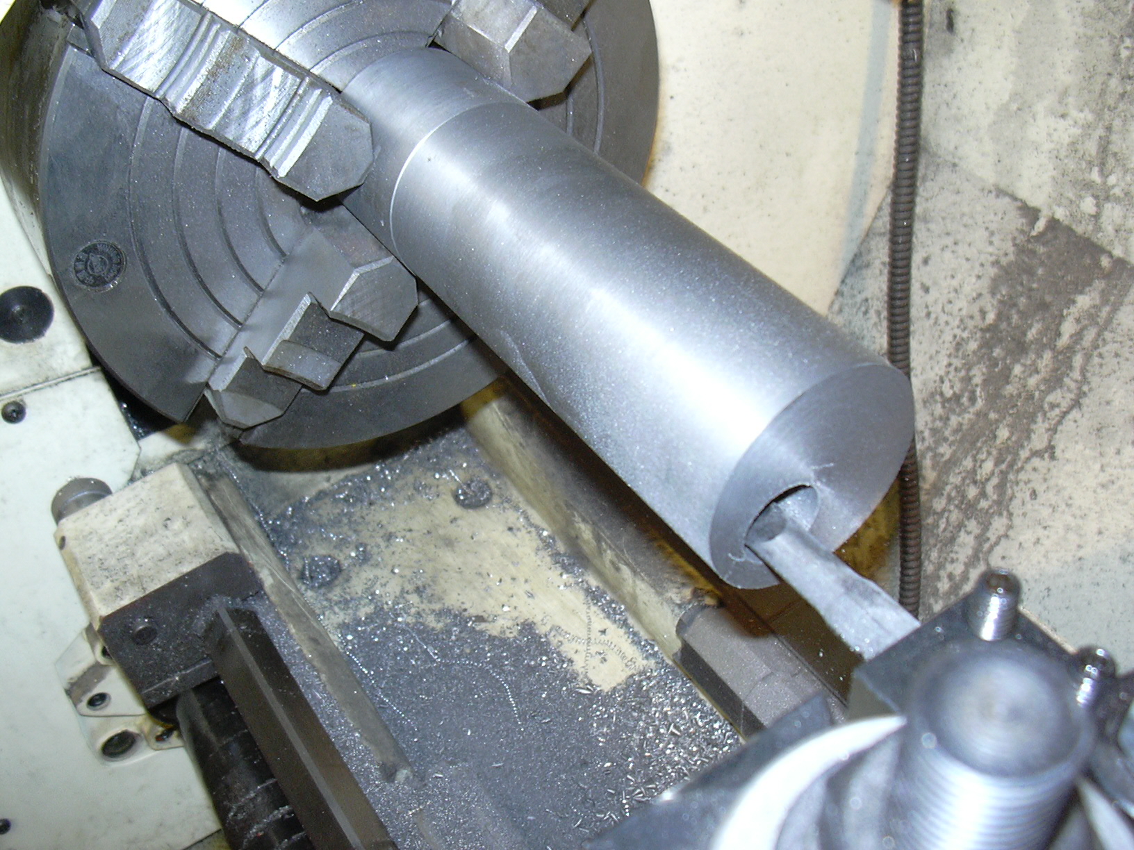
Fig 09 - Setting 4 jaw Fig 10 - Boring Eccentrics
Some jobs require setting the work-piece off centre. The job shown in Figs 10 started being chucked concentrically and turned to required finished diameter. The 4-jaw was then re-set with aid of DTI to the required eccentricity, the job was then drilled and bored. Finally, slices were cut off and faced to produce two sets of four eccentrics for a pair of miniature steam locos. There are other, possibly better, ways of doing this.
Would I buy the same lathe again? To answer this, let's review my original list of essential minimum requirements. All that's changed is the addition of 'Camlock', which it has. I've only a couple of trivial complaints against the Challenger. It came fitted with a chuck guard. No doubt this was an afterthought to comply with Health and Safety regs, but it was pretty useless as in most cases it caught none of the swarf, and I had to remove it anyway as the chuck jaws clouted it when holding larger work. I thought I might re-fit it a little higher, but … This is not to make light of safety. All machine tools are potentially dangerous, larger ones more so. Accidents using lathes of this size can and do result in life-changing injury or death.
The only other wish would be for variable speed control, and then only because the lowest speed of 45RPM is still a little scary for some screw cutting operations, many of which I do by disengaging the drive and turning the chuck by hand. The range of speeds is otherwise all I've ever needed.
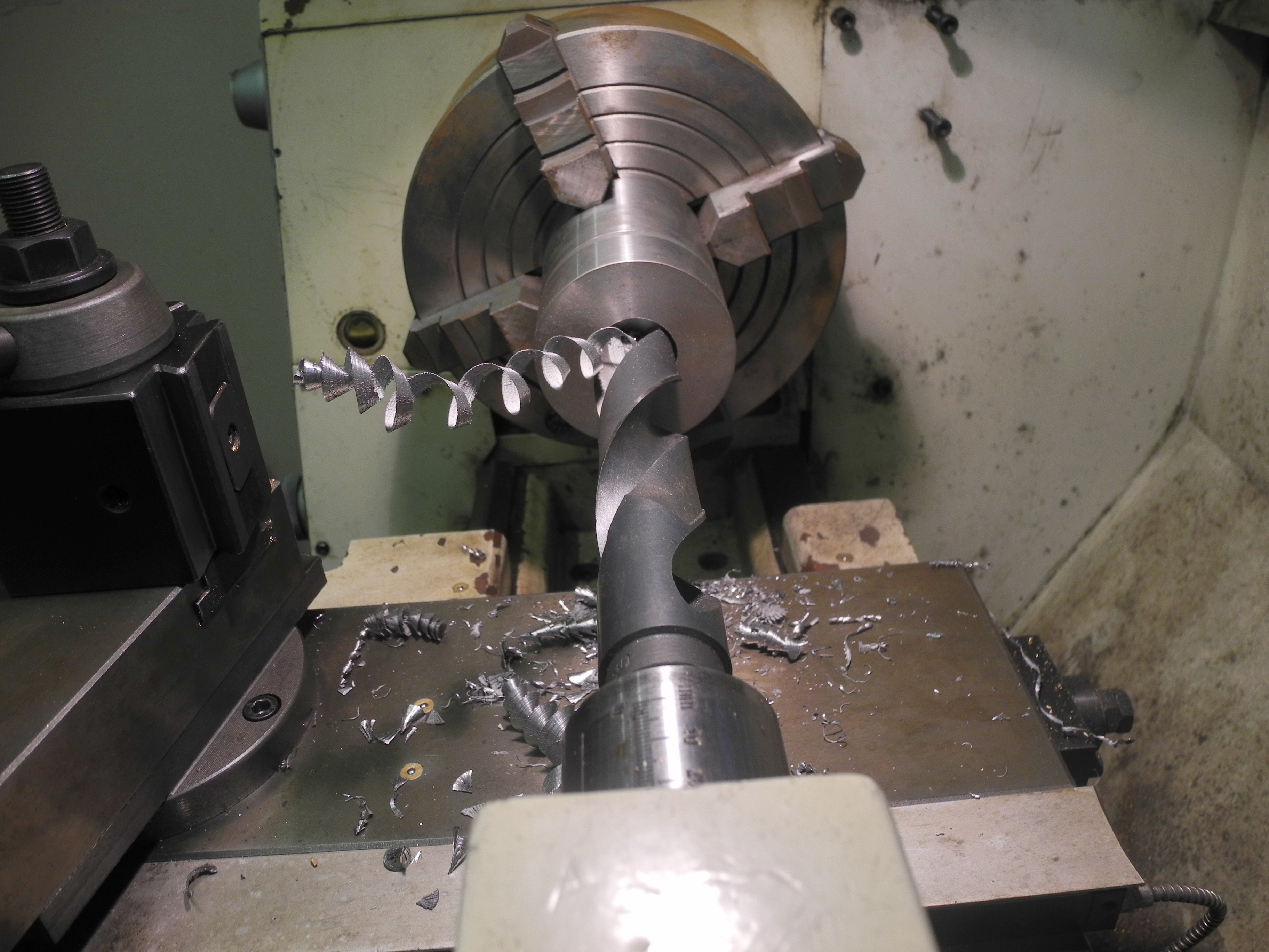
One day I realised I hadn't touched the small lathe, a Myford ML7, for more than a year. I placed an ad and sold it. I think this proves how satisfied I am with the Challenger for all tasks great and small, but to be honest I don't need a lathe quite this big and heavy, and the three-phase supply is an additional cost. This is a very large lathe by model engineering standards, rated for industrial use. It doesn't get anything like industrial use in my workshop and stands a good chance of remaining in near-new condition when the time comes for me to down tools. Fig 11 shows how quickly and effortlessly holes up to 30mm diameter can be drilled through steel, but that said, how often do I do this? If going out to buy a lathe today, I'd be looking for something about two thirds of the weight, half the price, and single phase. Not needing a lathe rated for continuous industrial use, from Chester I might look again at their “Crusader” or “Coventry” models, or from Warco the GH1236, GH1330, or similar. I would certainly choose another geared head lathe with 'Camlock' spindle. I would not choose a lathe with a 'T slotted' cross slide, for milling operations I use a milling machine – the right tools for the job!
Fig 11 - Drilling hole with 30mm drill
There are some turning jobs which are either difficult, time consuming or impossible using this, or indeed most common lathes. These include turning accurate curves of any type, tapered screw cutting, and machining tapers longer than the travel of the compound slide. It might sometimes be useful to cut special thread pitches which just cannot be set for, also a method for cutting multi-start threads would be useful. However none of these are pressing requirements, and all become easy using CNC technology, but that's another subject altogether.