Version 2 - October 2023
Electronic Brake and Precision Load PL2022
The PL2022 is a versatile variable DC load, capable of :
- Operting voltage range 8 to 80 volt
- Load current 0 to 15 amp
- Power dissipation 0 to 1000 watt
Maximum power dissipation is determined by heat sinking arrangements used to mount the 4 FQA36P15 power mosfets, the elements used to dissipate the power. See FQA36P15 data sheet for guidance.
Higher current or power ratings can be obtained by parallel connecting PL2022 modules.
The PL2022 has two modes of use :
- Voltage Clamp
- Constant Current Precision Load
These modes can be used together.
Voltage Clamp
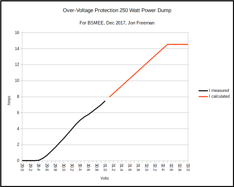
Voltage clamp mode has been used as a power dump to safely dissipate power from regenerative braking in traction applications. In some battery powered traction applications regenerated power is for preference stored back in the batteries. However this alone can not be relied upon as excessive charging currents may raise cell voltages beyond safe limits. In these cases, and in battery-less traction, the PL2022 clamps the system voltage to a safe level, dissipating power in the process. In this mode we can think of the PL2022 as a super high power Zener diode.
The clamp voltage, and the equivalent ESR (effective series resistance) are 'factory set' by the values of two resistors. A spreadsheet for calculating these values will be put up here once I get around to it.
Constant Current Precision Load
A positive voltage applied to the analogue input causes the load to attempt to sink a proportional current.
Potential divider R53, R6 scales input voltage to 0.0 to 1.0 volt at the non-inverting input to op-amp U2a, 0.0v causing a load of 0.0 amp, 1.0v causing maximum load as determined by other component choices.
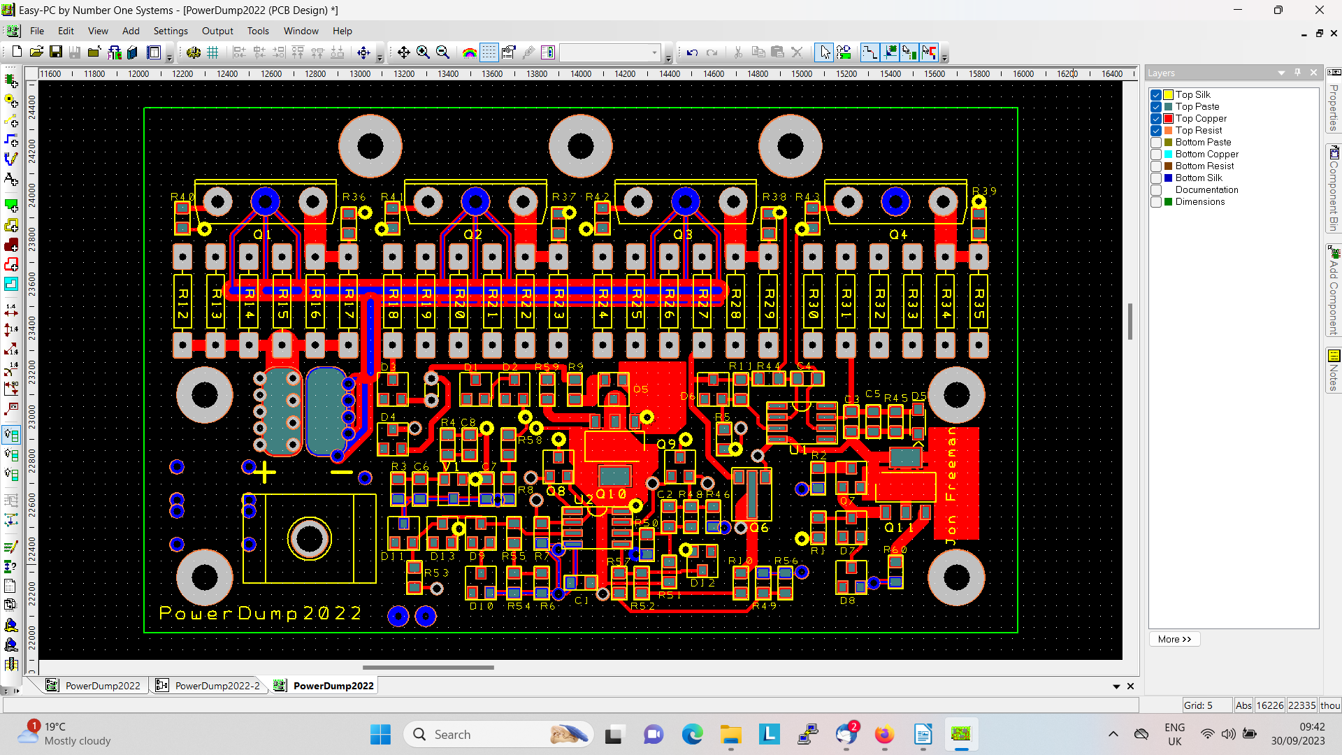
How it works - The Circuit
Get the schematic here.
Starting with the power stages and then working back - the schematic shows four paralleled power stages around power mosfet transistors Q1 to Q4. All four stages will be present for high power applications, although for lower powers, any number of stages (1 to 4) may be present.
Each power stage includes up to six 1.0 ohm current sense resistors (R12 to R35). Where more than one power stage is used it is recommended to use equal numbers of sense resistors per stage. Each current sense resistor fitted inceases full scale load current by 0.625 amp. Thus with all four stages fully populated the full scale current range will be 0.0 to 15.0 amp. You are of course free to use other (lower) value sense resistors, in which case you can work out the maximum load current yourself! (Higher values not advisable).
Sensed currents are averaged through R36 to R39, the result causing a potential difference proportional to current to be developed across R44, the ISENSE net will be between 0.0 volt at zero current and -0.5 volt at max current, with respect to the positive power input net POW+.
The load is activated when other parts of the circuit sink a current in the range of 0.0 to 0.5mA through R44. Operational amplifier U1 together with the power mosfet stages may be considered a unity gain non-inverting amplifier with ISENSE as the output. Thus a voltage developed across R44 will be 'matched' by load current sense derived feedback. Current in the range of 0.0 to 0.5mA sunk from net 'OA+' results in the module sinking a proportionate current in the range 0.0 to MAX (as determined by component choices) amp. Capacitor C4 (100n typ) limits frequency response and aids stability.
The schematic shows two circuits capable of pulling current down through R44 :
- Circuitry around U2a, Q8, R5 - Q8 will sink a current proportional to the voltage presented on the analogue input.
- Circuitry around U2b, Q9, R47 - Q9 will sink a current determined by the voltage of POW+ and component values around U2b which is configured as a high gain amplifier. This provides the voltage clamp function.
In voltage clamp traction use it may be convenient to keep power cables connected. This is fine, with jumper 'J1' not fitted and with no voltage applied to Testpoint PWR_ON, the unit draws negligible current, discharging typical traction batteries in many years. The unit is brought to life when PWR_ON is taken to > 8 volt positive through some 'ignition switch' or whatever.
Above is a bit sketchy but probably sufficient. Unexplained parts of the circuit form part of the material I was working on for a lecture "Current Sources and Sinks - how to use them". Any questions - ask.
The PL2022 builds upon experience with an earlier version. This is explained in detail below. Enjoy.