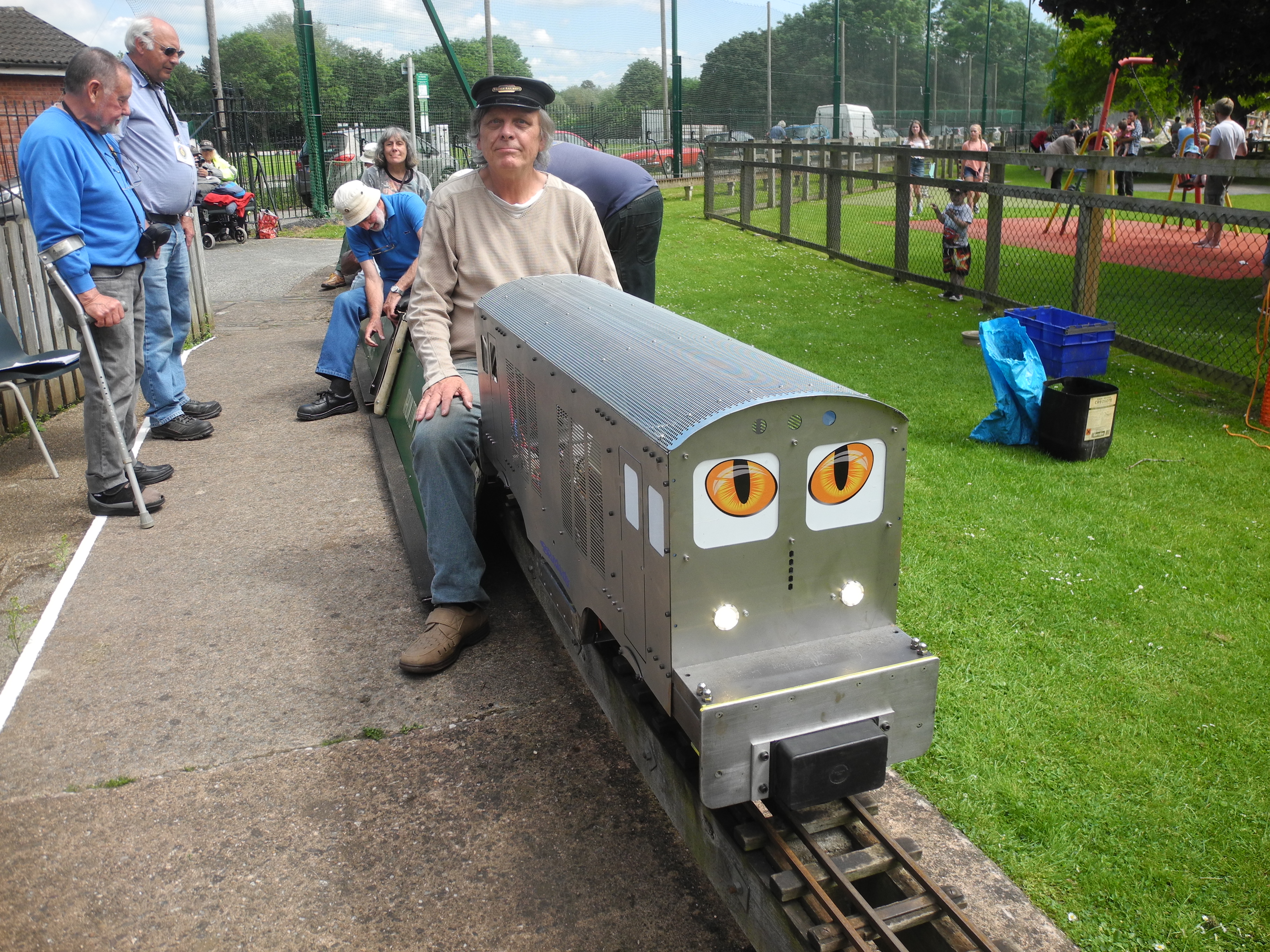
A Dual-Gauge Petrol Electric Locomotive using Brushless Motors in 71/4" and 5" Gauge - June 2018
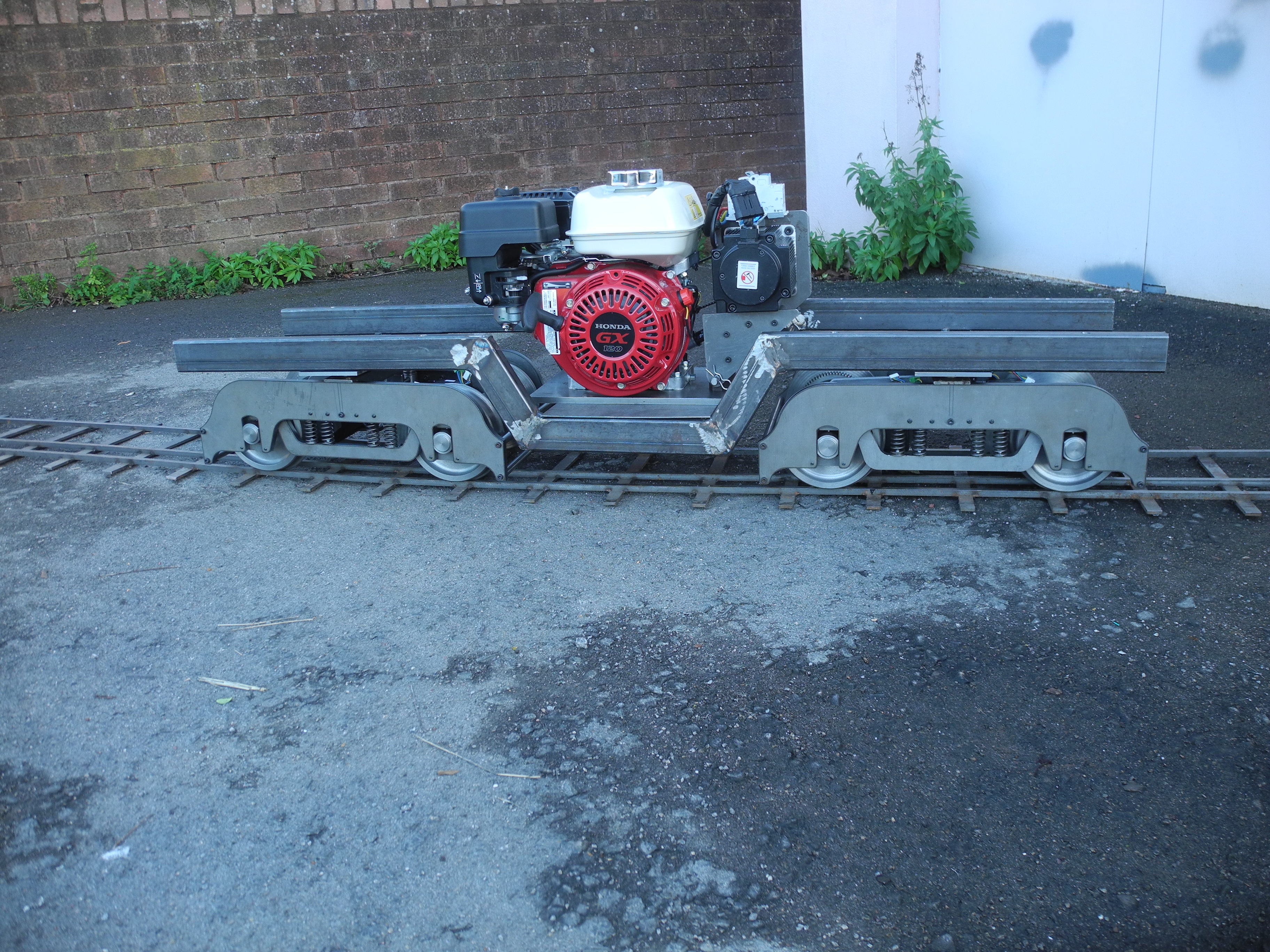
'Brushless Brute', Vivary Park, Taunton
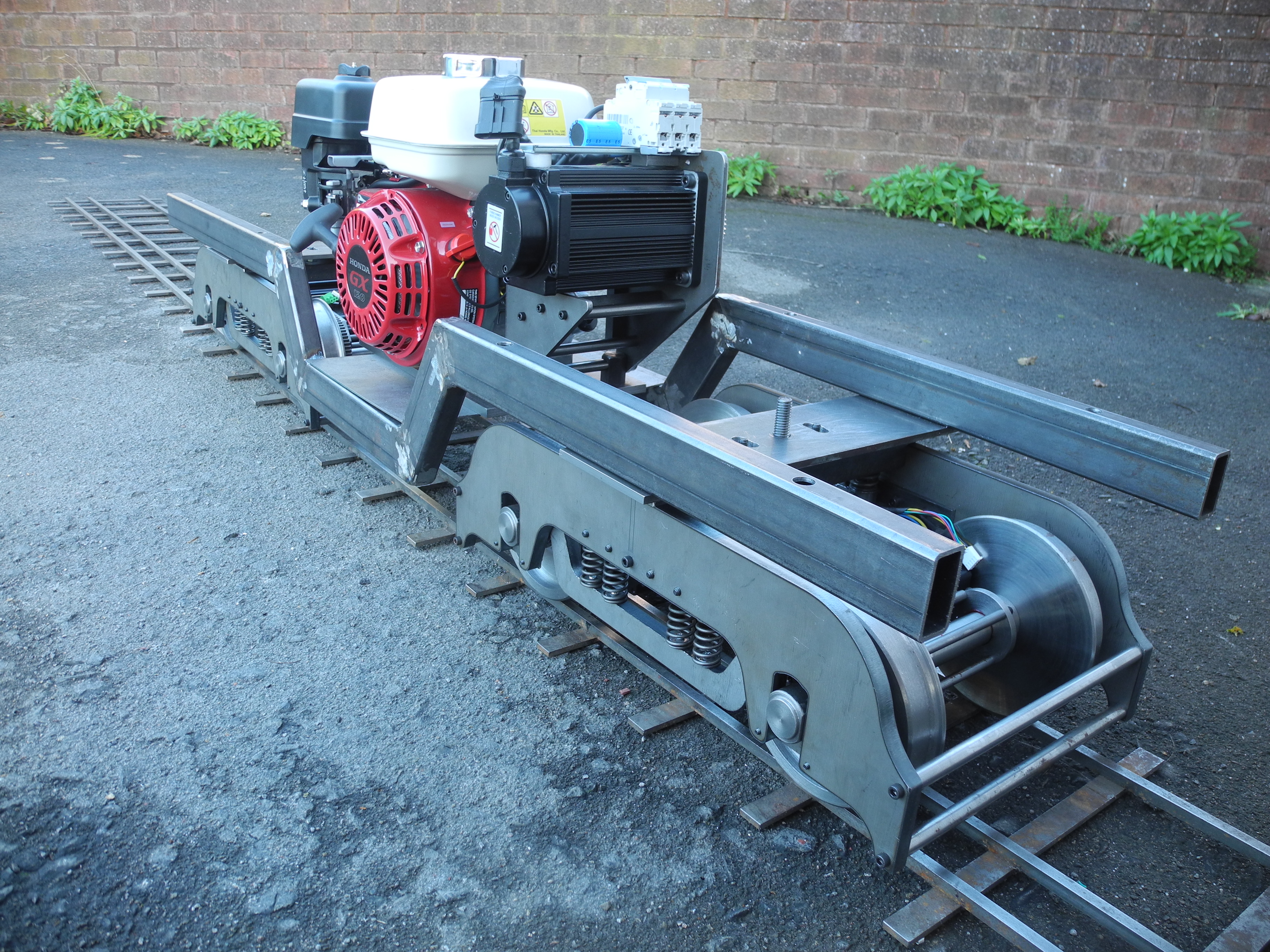
Two pairs of easily removable bogies enable simple gauge setting. Modular construction for ease of handling and assembly on site.
By the end of 2018 the loco has run in excess of 100 miles on the 5" bogie sets, and has proved capable of running for the whole five-hour session at Bristol using little over half a 2 litre tank of petrol!
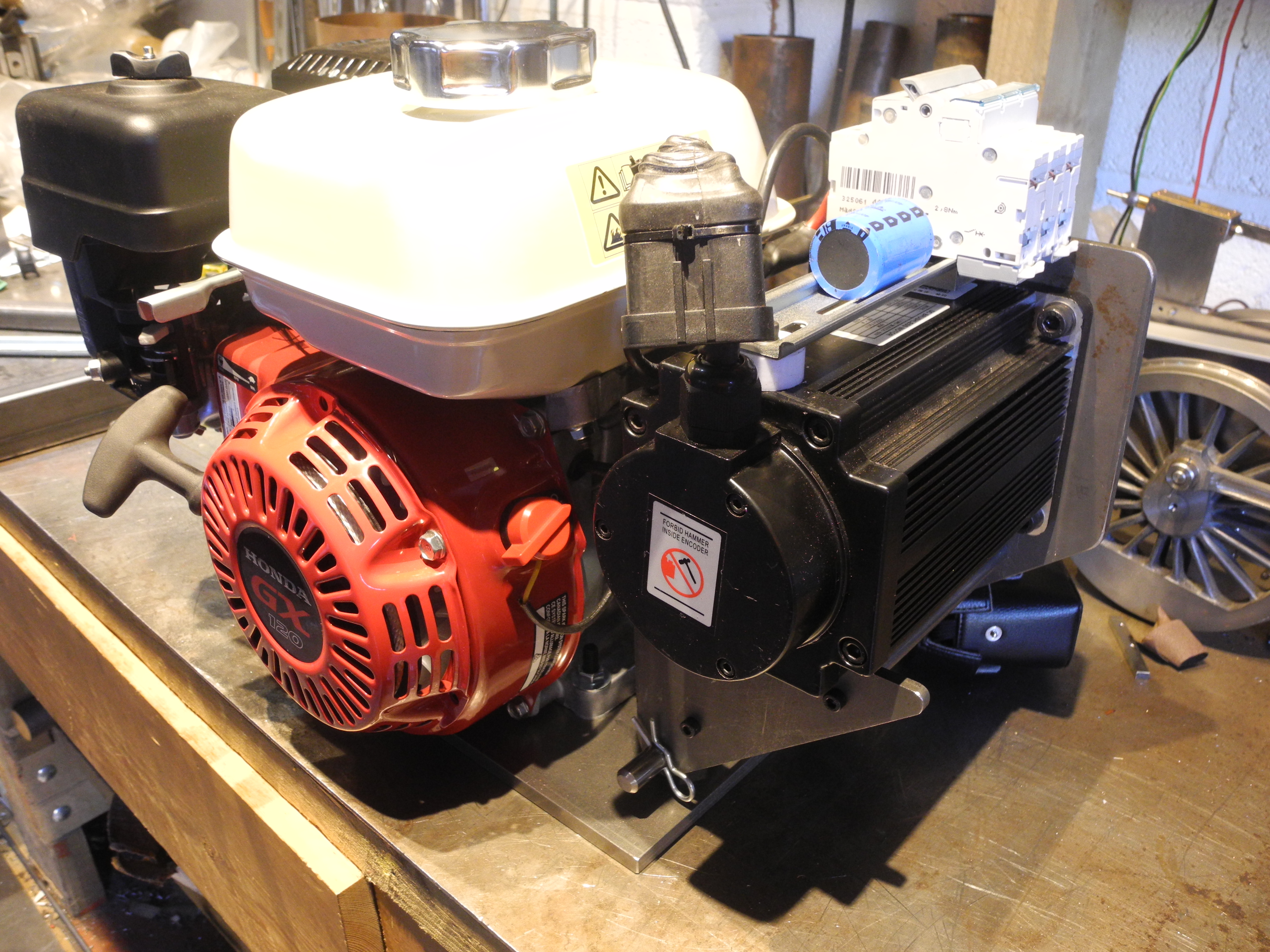
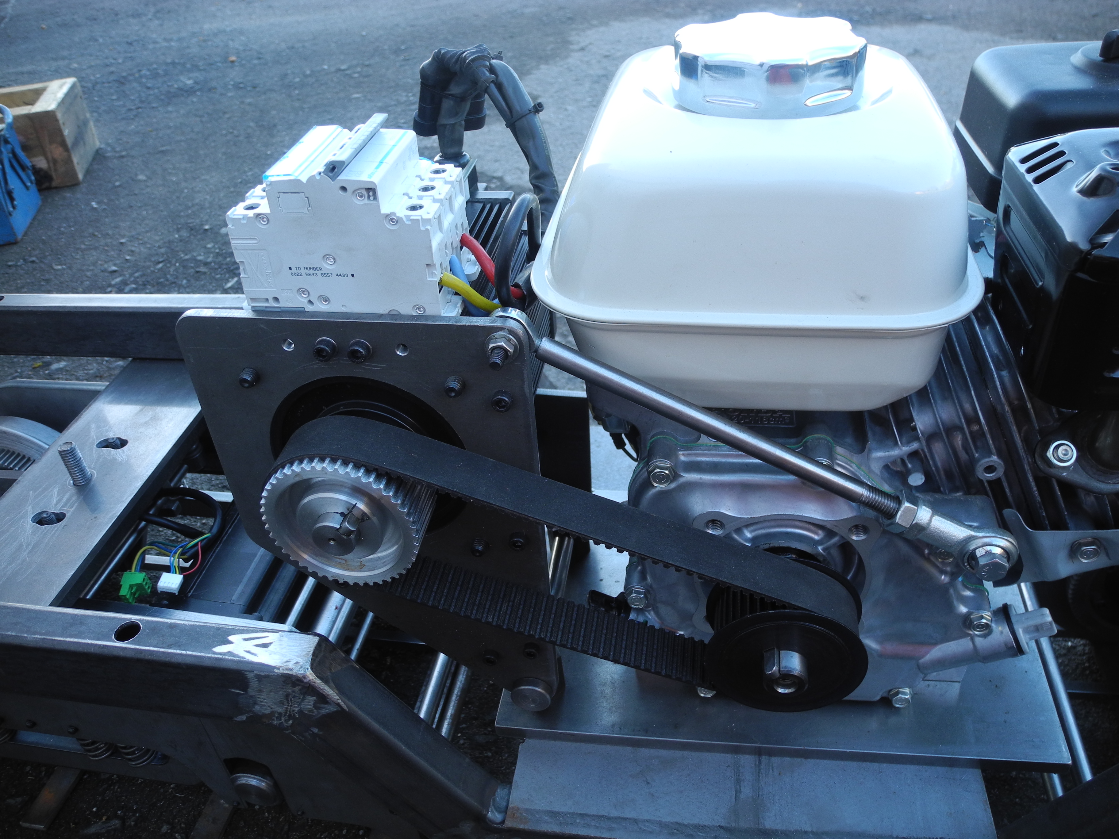
The Honda GX120 petrol engine belt-drives a 1.9kW three-phase brushless motor used as a generator - this forms the easily removable power unit. A battery or other power source could be used instead, but as designed with petrol generator, the 'Brushless Brute' has no need for any battery.
Honda GX120 Engine - Drives 1.9kW BLDC Motor as Generator
The brushless motor/generator was chosen for high efficiency of circa 90% - much better than typical vehicle alternators - although output voltage varies with engine revs from around 20v at tickover to a high of 55v. Traction motors are driven by a revolutionary new design of Electronic Motion Controller (EMC), the STM3 (see 'Electronics' pages), designed to operate on a wide supply voltage range from 10 to 62 volts.
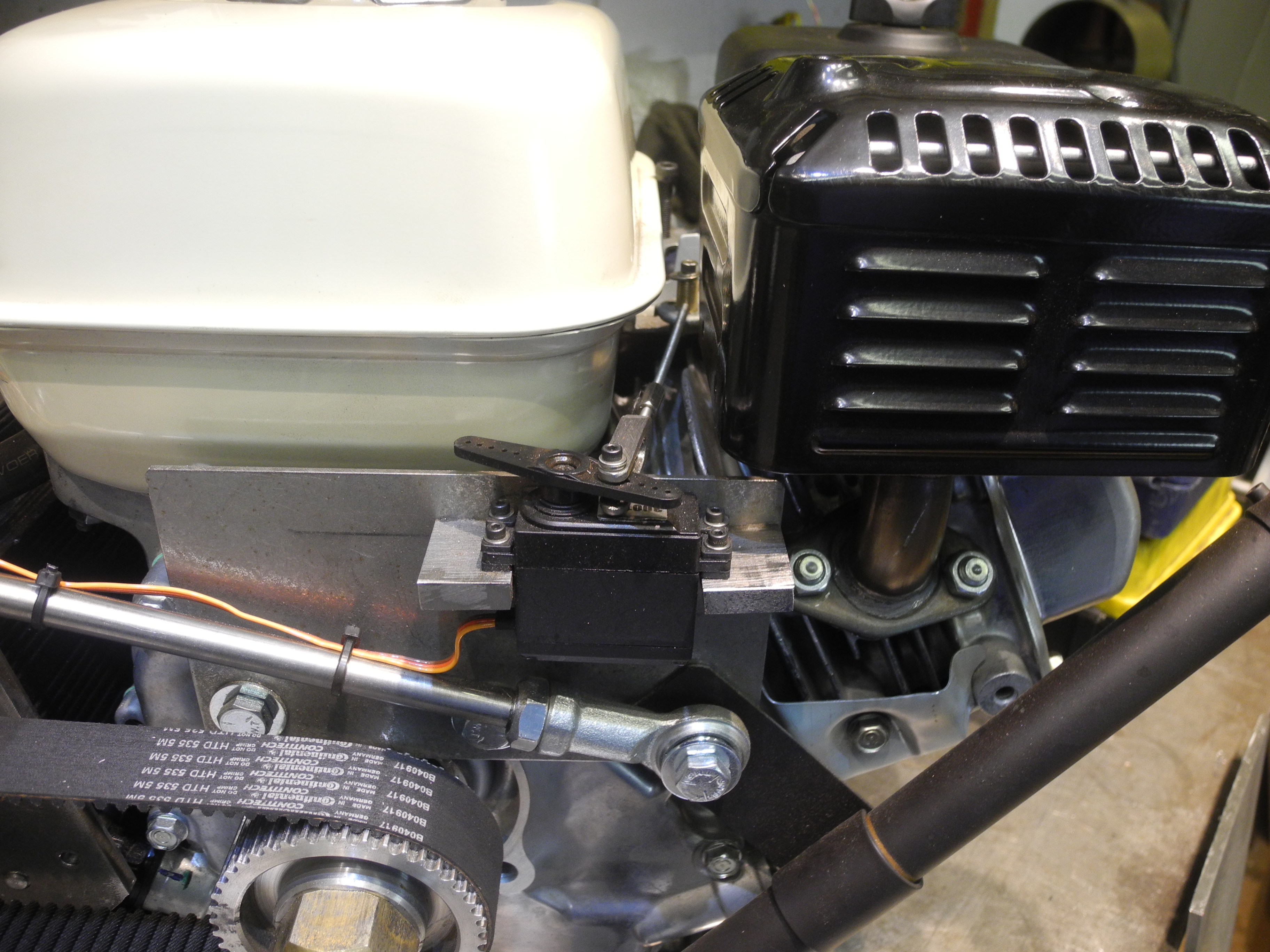
Engine speed under computer servo control
The electronics controls the Honda engine using a model control servo, and the train typically purrs around the track with the engine running not much faster than tickover. In practice, the higher engine revs needed to generate the highest voltages are rarely needed, only when pulling heavy loads up gradients at speed.
There is no battery in this design - this was one of the design criteria. The loco is started-up using the pull-cord starter on the Honda. Once this starts, power is available for the control and other systems. So far this has proved very reliable. The engine starts on the first pull and has run for periods of several hours at a time.
The longest run so far was on 28th May at Ashton Court, Bristol. The engine ran for more than the whole 5 hours of 'public running', covered a distance of 16 miles, consuming a little over one litre of petrol.
The latest spreadsheet (Jan 2019) containing all the detailed design calculations is here
Here are a couple of vids of Bob driving at Ashton Court, Bristol, 28th May 2018
Software Code is under constant upgrade. Contact Jon for further information.
Update June 2019
Although two bogie sets have been built for 5" and 71/4" gauge, the power is better used, and the whole driving experience feels somehow better on the broader gauge. Vacuum brake equipment has now been fitted ready for public running duty at the Bristol SMEE Ashton Court Railway. The larger bogies have been re-built to include steel guards enclosing the drive gears - this should greatly reduce the known danger of something getting flicked up into the gears with any consequent damage. The STM3 motor controller boards are now enclosed by fabricated polycarbonate enclosures, this keeps most of the rust and other undesirable detritus off the circuit boards while allowing the LEDs to be clearly visible - handy to check for correct power and operation.
A 'speed limit' function has now been built in. The loco speed limit can be set to any speed from 2 to 12 mph by tapping codes into the touch screen controller. Jon said; "No I'm not telling how to set the speed limit, this is my little secret, and was put in place for when I allow our junior members loose with the loco!"
June 2nd 2019 - Today was 'Club Running Day' at Ashton Court Railway, and was to be the final test run prior to entering public service on the ground level track at Ashton Court. After a a few laps pulling two trucks, the vacuum brake gear was proved to be good, the speed limit function seemed to work, and all was well until the rain set in. For the first time it was found that the touch screen doesn't like being rained upon. It stopped responding to 'touch' until thoroughly dried out. Sadly off for an early bath.
More to follow soon, all below here is old stuff cobbled together during the design and build, a bit of the history.
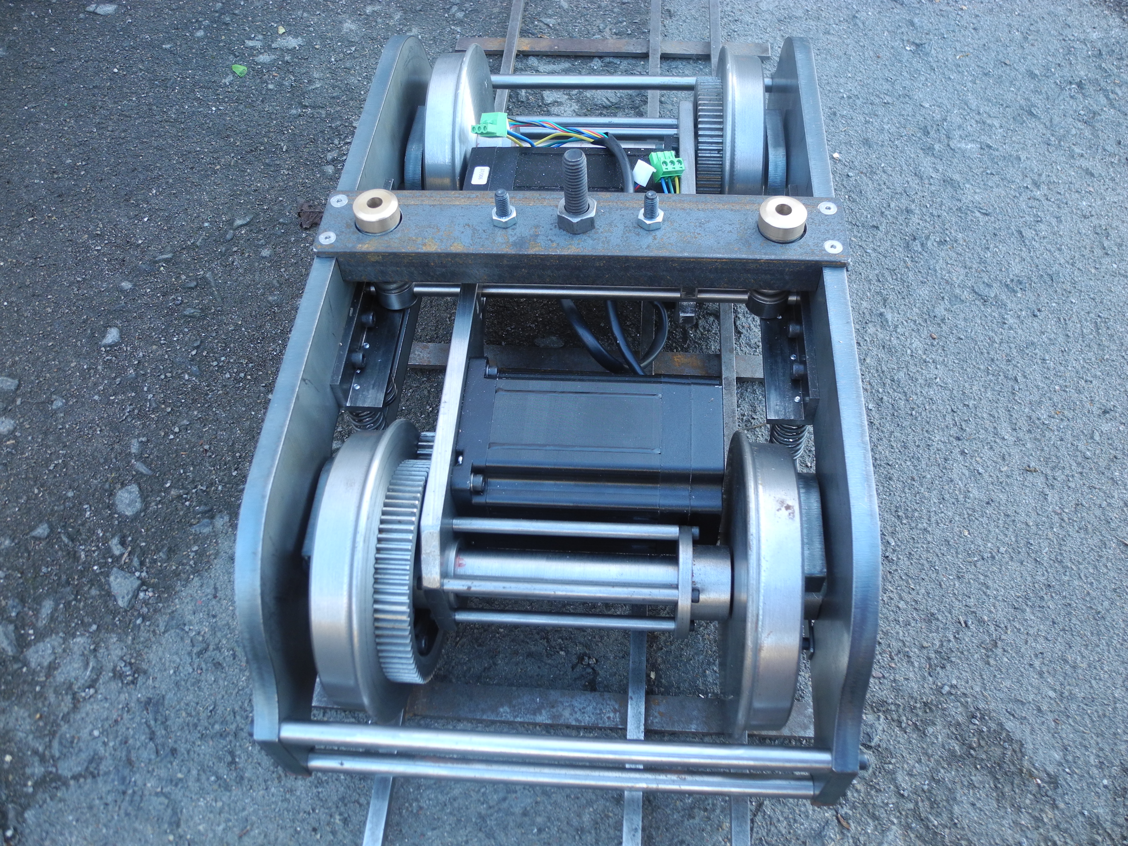
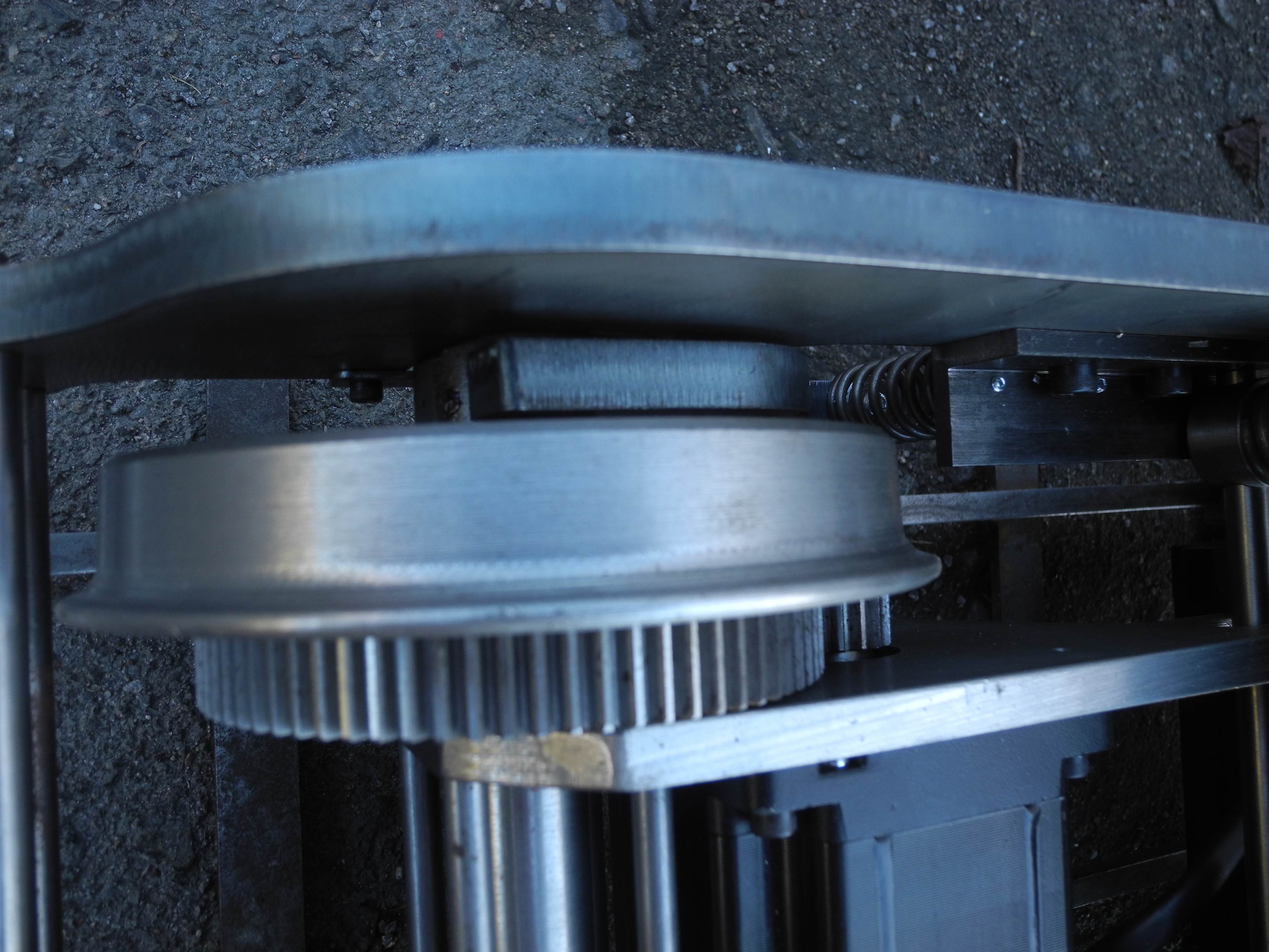
Bogie with 660 Watt BLDC motor per axle All steel gear drive (1.5 MOD)
Bogies completed October 2016
Frame length 1440mm. A bit short, but then it has to fit in the car.
But what of batteries?
There are plenty of locomotive designs that use some generator with batteries - same idea as hybrid cars. This is justified where batteries alone would unduly limit range, or where the generator has insufficient power for all loads and conditions.
The petrol generator shown here is easily removable - the whole point of modular design is to allow for quick and easy assembly / disassembly for one-man handling and ease of transport.
A pair of 12V 50AH gel batteries (as used in mobility scooters) could be dropped into the well in place of the petrol gen, and there we have a battery-electric locomotive !
There's plenty of space to fit up to another six such batteries, 3 in front of and 3 behind the centre well, however the wheelbarrow full of cash to pay for these is absent.
Another option - batteries could be fitted in front of and behind the petrol generator.
Flexibility is part of the design philosophy, multiple alternative power sources, wider range of possible uses.
Bogies, Chassis, Power Unit ...... Modules Coming Together Xmas 2016
Electric motors are also usable as brakes. Using a system of 'Regenerative Braking', the motors can also behave as generators, but where is this regenerated power to go?
In a battery-electric design, some of this power can be put back into the batteries - very good, but this is not effective with fully charged, or near fully charged, batteries. Without anywhere else to 'dump' any unusable regenerated power, the system voltage can easily rise beyond safe limits. Any robust electric locomotive design will therefore, include some over-voltage sensing, and voltage limiting, power dump.
Design calculations indicate the petrol gen, electronics and brushless motors alone will give more than enough poke for useful duty hauling passengers around a club track, and a full tank of petrol should last a long afternoon or thereabouts.
Calculations also indicate the torque deliverable to the wheels is well above that likely to induce wheel-slip. Should this prove a problem, batteries may be added - as ballast !
A spreadsheet of design calculations can be seen here As you can see, the loco should be able to accelerate a load of 2 tons up a 2% gradient. Please download and play with loads and gradients etc.
Toothed Belt Drive Computer Control Panel coming on
Video shows one bricked-up bogie on the test bench.
The bench power supply is only capable of delivering 5 Amp at 31 Volts. In regular use, the bogie may be expected to draw up to about 35 Amp from 48 Volts. Note when the hand appears and slows the axle, this is because the bench supply collapses under the load !
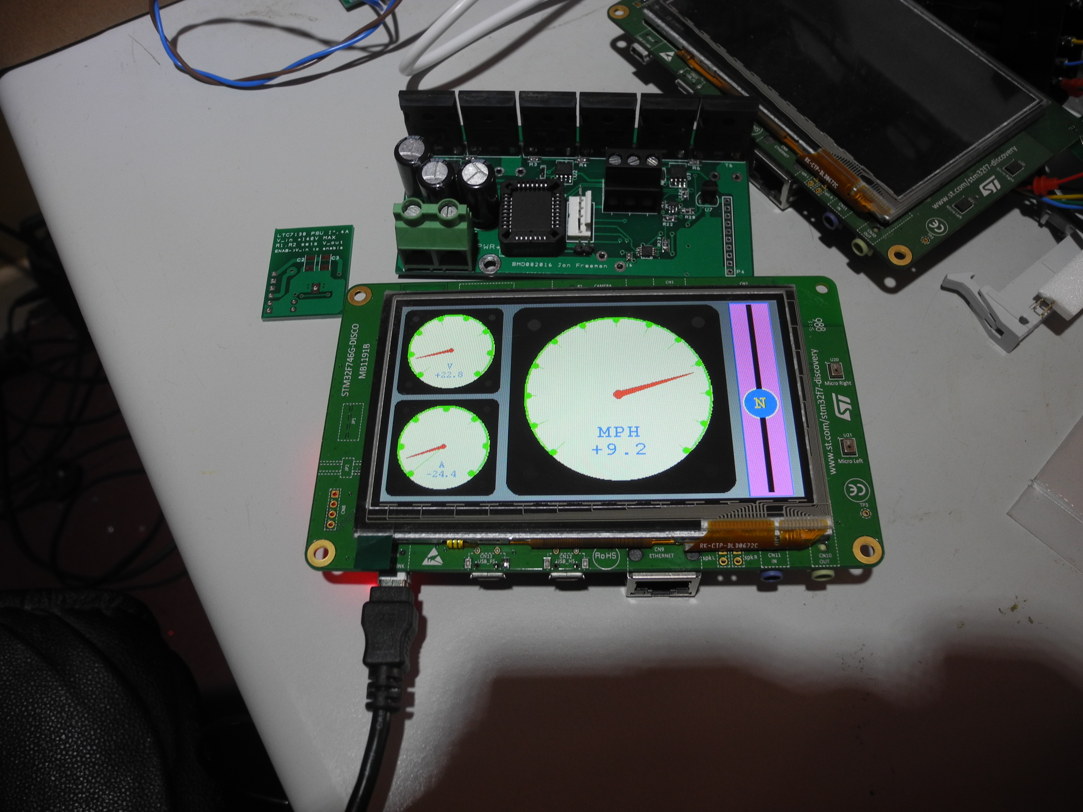
The slider control seen to the right side of the touch-screen display will be the normal drivers control. Moving a finger over the slider towards the top and the loco will move. Taking a finger off the slider causes the control to drift back to the 'neutral' position and the loco will glide gracefully to a halt. This meets the 'Dead Mans' function required of electric locomotives on club tracks. For purposes of this test, the buttons 'hidden' behind the voltmeter and ammeter are used to increase / decrease speed.
Below, a very simple power dump for use with regenerative braking.
When the applied voltage is below the zener diode voltage, no voltage is developed across R1, no voltage is applied to the mosfet gates so nothing conducts. As applied voltage rises, the zener passes current developing a voltage across R1 which is applied to the mosfet gates. Once this voltage exceeds the gate threshold voltage, current starts flowing through the mosfets. Resistors R2, R3 etc tend to equalise current through each, and also tailor a not too vicious response to rising voltage.
Any number of mosfets with equalising resistors may be connected in parallel, for this loco design there are 20, each capable of dumping around 50 Watt. (I had considered designs using high power wire-wound resistors, mosfets are much less expensive !).