It would be easy to fall into sloppy habits when talking about movements and positions in the three dimensional machine space, better to be precise and clear. The DROs (digital readouts) on the Mach3 screen can only report the position of one particular point in the three dimensional machine space at any instant. This is known as the 'controlled point', the point whose rate of movement and position are controlled. This will normally be on the axis of the spindle some distance below such that when using a flat ended tool such as an end mill or slot drill, the controlled point will be chosen to be at the cutting end of the tool along its axis (and so in the centre of the cutting face). When using other tools a different controlled point may be chosen. When using a ball nose cutter for example, the centre point of the tool ball may be chosen as the controlled point. Worth remembering, the controlled point is often not any point where cutting is taking place but somewhere near, this will depend upon the tool geometry.
Testing a Code Fragment
Once familiar with the look and feel of Mach3, the next step is to create and try out some simple G-Code programme fragments just to prove it all works. This involves creating a text file, saving it to disk somewhere you will be able to find it again, loading it into Mach3 and seeing what it can do. A good plan is to create a new folder somewhere on your PC just for your programme files – keeps them out of the way of everything else.
Having created or decided upon a folder in which to keep files, 'Notepad' or other plain text editor of choice may be used to create a file containing a few code lines, for example :
 G0 X0 Y0 Z0
 G1 Y3
 G2 Y2 J-0.5
 G3 Y0 J-1
Saved using a file name such as “demo1”, this may be loaded into Mach3 from the main Mach3 screen by clicking on the 'Load G-Code' button, navigating to where the file was saved, selecting and clicking 'Open'. (Full descriptions of these and all other G code instructions are contained in the Mach3 documents).
With this example “demo1” file loaded the Mach3 screen should closely resemble Fig 305. If no curly shape shows in the tool path panel, an error message may be shown in the 'Status:' bar near the bottom of the screen indicating which line in the file Mach3 cannot deal with. Common mistakes include use of letter 'O' or 'o' instead of figure '0' – this G code fragment should contain zero letter 'O's, and six figure '0's (also two figure ones '1', and no letter 'I' or letter 'l' characters)!
With an error free file loaded, the four lines of G code will be visible in the grey programme panel top left, and the tool path panel, top right, will display a vertical line and a pair of connected semi circles. The programme fragment may be run by clicking on the green 'Cycle Start' button. A simulated run should commence. In the programme window, the line of code currently being run will be highlighted. The numbers displayed by the set of DROs will constantly update reporting the controlled point position, and the cross-wires in the tool path window will show where the controlled point is and how it is moving.
Having seen Mach3 perform a few simple operations such as these, it's time to write a first real programme. One way to programme is to write a long 'join-the-dots' list, a method known as 'in-line' coding, one code line for each straight line or arc movement. However, many jobs lend themselves to alternative methods which involve writing some very compact 'loop' code, easy to read, easy to write and easy to understand.
Writing G Code Programmes by Hand
Fig 305 - Mach3 Programme Run screen with code fragment
Before concerning ourselves with detail, syntax and limitations of any programming language, a first stage in the creation of any CNC programme is to think through a logical, workable sequence of cutting actions to achieve the intended outcome. Writing notes listing the sequence of actions is the logical next step – think of this as creating the programme list in a plain English pseudo-code. This may be done using a pencil and the back of an envelope, although good programme design is, more often than not, an iterative process – looking back and making improvements, and there's only so much crossing out and scribbling any one envelope can take! Using a Notepad-like text editor is much easier once you're used to it and saves time at the next stage. Once satisfied with the pseudo-code listing, this may be translated in an almost line-by-line style into a language the Mach3 machine can understand and use – G code in this case.
While this in-line 'join-the-dots' style may suits simple projects, trying to read, understand, modify and reuse such long list programmes becomes exponentially more difficult as the programme list gets longer.
Managing Complexity
Safe, useful, reusable programmes tend to be short and easy to understand. They will include ample plain language comment sufficient to explain what the code ought to be doing. They will use 'parameters' to store numbers, and will include 'subroutines' (also known as sub-programmes, functions or procedures). These three features – comments, parameters and subroutines – are powerful tools that can be used to create action-packed programmes using surprisingly little code.
Comments
Some programmers write reams of code and then go back and add comments almost as an afterthought. The method advocated here is the exact opposite, with code development being encouraged first of all in a plain language 'pseudo-code', written into the code file as pure undiluted comment. Once happy with the written description, only then are the pseudo-code comments translated and copied into G code. This usually involves some revision or rephrasing of the pseudo-code to fit the capabilities of the G code language. This method tends to lead to the production of reasonably compact code, but most importantly, code the programmer or another reader will be able to understand next week and next year.
Mach3 G code allows alternative methods for including comments. For simplicity, one method will be used exclusively in this text, the semi-colon ';'. Anything on a line in the file following a semi-colon is a comment. For example, if the file contains the line:
G1 X3.25 ; Move X axis only
The G1 code informs Mach3 that a straight line movement is intended at the most recently set feed rate, and the X3.25 specifies the move affects only the X axis and the move is to position the controlled point at X coordinate +3.25 leaving the unmentioned Y and Z coordinates unaffected. The semi-colon and following text are the comment, intended to help the reader understand what the programme is supposed to do.
While writing the initial pseudo-code, starting every line with a semi-colon is a good idea.
Before getting into detail of the other big weapons in the armoury - parameters and subroutines – this is a good point to create a reusable programme template containing all the set-up preamble and other stuff common to all or most programmes, and to follow on with the development of a “circular_hole_miller” programme using the in-line, 'join-the-dots' style.
Building a Real Programme – Using a Template
Using a programme template is a sensible place to start a new programme.
The listing below shows one possible structured programme template saved as a file named “G_code_programme_template.txt” : -
 ; Programme File Start
 ; Preamble - puts machine into known, safe state
 G17 ; Select XY plane
 G21 ; Units are mm, use G20 for inches
 G40 ; Cancel cutter radius compensation
 G49 ; Cancel tool length offset
 G61 ; Exact stop
 G50 ; Reset all scale factors to 1.0
 G90 ; Absolute distance mode
 G94 ; Feed mm per minute - mm selected by G21
 ; Machine now set into known, safe state
 ; User Interface Start
 ; Programme Title :
 ; Date :
 ; Author :
 ; Why was this programme written?
 ; ...
 ; What does the programme do?
 ; ...
 ; Any other useful information?
 ; ...
 ; Assign users numbers to 'parameters' here
 ; User Interface End
 ; Programme code goes below here

 M5 ; STOP Spindle
 M30 ; END PROGRAMME and Rewind

 ; Place any Subroutines below here
 ; Programme File End
This has built upon the basic structure idea developed in the previous article to include a set of G code instructions in a 'preamble' used to set the system into a known, safe state, and 'M' codes M5 and M30 used to safely stop the spindle, end the programme and 'rewind' ready to run again. The G codes listed in this preamble have proved satisfactory for the examples illustrated here using a Sieg KX3 CNC machine. Before using on any CNC machine, the programmer should check documentation for their system, other set-up configurations are possible, not all will be safe, it is your responsibility to check! Once a template programme similar to this has been created and saved, each new programme may be started by loading the template into the text editor, saving a copy using the name of the new programme being written, adding programme code and saving again – keep a copy of the original template programme somewhere safe ! Copying the exact template as shown or modifying it to your own requirements, once saved it can be loaded into Mach3 which, all being well, will report no errors in the 'Status:' bar, and produce no trace in the tool path panel. Running the code by clicking 'Start' should cause the template code to scroll up through the programme panel before returning to highlight the first line.
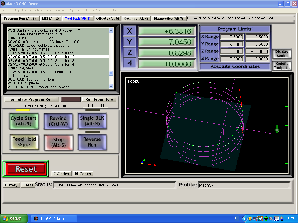
Building a 'round_hole_miller' programme – in-line style
Fig 308 - Mach3 tool path window
For a first example of a real programme, a hole of 25mm diameter is to be milled to a depth of 8.0mm using a cutter of diameter 6.0mm, moving the tool down through four spiral turns and ending with one circular turn.
This simple programme is easy to think through in pseudo-code and write, as comment, into a copy of the template file. For simplicity, assume for now the required hole centre is at X and Y coordinates 0.0, 0.0. Assume also that a height of any positive Z value is clear of the work, the work surface is nominally at a height Z=0.0, and therefore, Z=-8.0 at the bottom of the hole. One plausible pseudo-code could be : -
 ; Programme code goes below here

 ; ** Pseudo-code Start**
 ; Ensure tool raised clear of job
 ; Set spindle speed and start
 ; Set tool feed rate
 ; Move to cut start position XY
 ; Lower tool to start Z position
 ; Cut spiral turn, four times
 ; Cut circle, once
 ; Lift tool clear
 ; Stop and End
 ; ** Pseudo-code End**
That looks as if it covers all the requirements and could be typed into a copy of the template file, the next task is to add G codes to perform the actions identified. The main Mach3 screen has buttons labelled 'G-Codes' and 'M-Codes', just to the right of the large 'Reset' button. Clicking on these reveals detail of all the codes needed, more thorough explanations may be found in the Mach3 documentation.
First, the current position of the controlled point is assumed unknown. The first line '; Ensure tool raised clear of job' is a precaution to make certain the tool is clear of the work. A sufficient G code with comment would be :
G0 Z10.0 ; Raise tool 10mm clear of work
This uses the G0 rapid move code to lift the tool clear to height +10mm. Next the spindle speed and feed rate may be set and the spindle rotation started :
 S660	; Spindle 660 RPM
 F50	; Feed rate 50mm per minute
 M3	; Start spindle clockwise at 'S' RPM
Optimum spindle speeds and feed rates will depend upon the tool in use and the material being cut, the figures here were used to cut steel using a 6mm cutter as seen in Fig 301. Including comments as here is a habit to get into.
 ; Move to cut start position XY
 G0 X? Y?  ; Move to where?
 ; Lower tool to start Z position
 G0 Z+2.0  ; Tool down to 2mm above job
Moving to the start position requires knowledge of how the following 'Cut spiral turn' will work using the G2 or G3 codes. In common with G0 and G1 codes for straight line movement, any one or more of X, Y and Z values may follow G2 or G3 to specify required controlled point position at the end of the cut. When cutting circles, the X, Y and Z values at the beginning and end of the cut will be the same. By changing the value for Z, a spiral cut is obtained. From this it can be seen the X and Y values used in G2 or G3 will be the same as those used in the '; Move to cut start position XY' line above. Note the Z+2.0, this will cause the rapid tool movement downwards towards the work, to stop 2mm above the nominal face of the work. This allows a small safety margin against crashing the tool into the work at high speed and will lead to the cut gliding smoothly into the surface when cutting the first spiral turn.
G2 and G3 can be used in either of two basic modes : Radius Format Arc, and Centre Format Arc (see “Mach3Mill_1.84.pdf document, section 10.7.3 for full detail). The Centre Format Arc is favoured here as Radius format can not be used to cut complete turns in a single instruction. In addition to the X, Y and Z values, centre format mode G2 or G3 code uses the 'I' and 'J' terms to indicate the X and Y offset of the arc centre from the circle start and end point. Using the defaults already selected in the 'preamble' section, we may use the Centre Format Arc form:
G2 X? Y? Z? I? J? ; Comment
where the '?' are replaced with the numbers for our application, once we know what they are.
We have free choice as to where on the circle to start and end, it matters not a jot, however a wise choice – habit to get into in situations such as this – may be to choose compass point East, to the right side of the circle. This is because by mathematical convention, this coincides with an angle of zero degrees from the centre. It makes no difference for this simple case, but might help reduce confusion in later work when angles or trig functions such as sine, cosine or tangent crop up.
Working through the list of five '?'s - with a hole diameter of 25.0, a tool diameter of 6.0, the tool path diameter is therefore 25.0 – 6.0 = 19.0mm, the tool path radius is therefore 9.5mm. The 'East'-most tool position will then be at X = +9.5 and Y = 0.0. These figures may now be plugged into the '; Move to cut start position XY' line :
 ; Move to cut start position XY
 G0 X9.5 Y0.0	; Move to XY, leave Z at 10.0
 ; Lower tool to start Z position
 G0 Z+2.0	; Tool down to 2mm above job
Working out G2/G3 'I' and 'J' values, in this case the X offset 'I' = -9.5 as the centre is 9.5mm to the left of the start and end point, J = 0.0 as the centre, start and end all have the same Y coordinate value (0.0 in this case).
This leaves only the Z values to work out. Four turns of spiral take the Z coordinate from +2.0 to -8.0, a change of 10mm, divided by 4 gives 2.5mm per spiral turn. We may now write directly, G codes for the four turns of spiral :
Repeating the final spiral turn line unaltered (with no change of 'Z' coordinate) will finish the job with the circle.
 G2 X9.5 Y0.0 Z-8.0 I-9.5 J0.0 ; Final circle
 G0 Z10.0	; Tool up and clear
 M5		; Stop spindle
 M30		; End programme and rewind
Bringing this all together, the text inserted into a copy of the template file is shown in Fig 307.
  ; Programme code goes below here

  ;Next, add G codes to perform actions identified.
  ; Ensure tool raised clear of job
  G0 Z10.0 ; Raise tool 10mm clear of work
  S660 ; Spindle 660 RPM
  M3 ; Start spindle clockwise at 'S' above RPM
  F50 ; Feed rate 50mm per minute

  ; Move to cut start position XY
  G0 X9.5 Y0.0; Move to start XY, leave Z at 10.0
  G0 Z+2.0 ; Lower tool to start Z position
  ; Cut spiral turn, four times
  G2 X9.5 Y0.0 Z-0.5 I-9.5 J0.0 ; Spiral turn 1
  G2 X9.5 Y0.0 Z-3.0 I-9.5 J0.0 ; Spiral turn 2
  G2 X9.5 Y0.0 Z-5.5 I-9.5 J0.0 ; Spiral turn 3
  G2 X9.5 Y0.0 Z-8.0 I-9.5 J0.0 ; Spiral turn 4
  ; Cut circle, once
  G2 X9.5 Y0.0 Z-8.0 I-9.5 J0.0 ; Final circle
  ; Lift tool clear
  G0 Z10.0 ; Tool up and clear
  M5 ; STOP Spindle
  M30 ; END PROGRAMME and Rewind
  ; Place any Subroutines below here
  ; Programme File End
This was then saved to a file named “hole_miller_inline.txt”. Loaded into Mach3, the programme listing (the top few lines of) are visible in the programme panel, and a circle is traced in the tool path window. Switching to the Mach3 'Tool Path (Alt-4)' screen shows a bigger version of the tool path panel. Moving the mouse pointer across this area while pressing the left button rotates this tool path image enabling you to see it from many view points – a most useful feature. A little time could be well spent playing with this feature while referring to the relevant section of the Mach3 documentation to get a working familiarity with all the move, zoom and rotate capabilities on offer. Fig 308 shows a rotated view of the four spiral turns finished off with a circle. It seems we have a working programme. Click on 'Cycle Start' and a simulated cut run will begin. The programme was running when the Fig 308 screen shot was captured.
Time for a cup of tea to celebrate our success, and the next exercise will be to turn this into something more versatile and easier to re-use.