Some time ago, I embarked upon a study of petrol electric power systems used in 5” and 7.25” locomotives, looking in detail at how they work, and why performance so often falls short of expectations. This work is now almost complete, and thanks to Bob Lilley and Andy Harding, a grand day out was had at Ashton Court on 22nd July 2020. The purpose of the day was to prove in practice an idea that had evolved along the way, a Low Cost Locomotive design. This uses an engine driving a modified vehicle alternator, wired directly to DC traction motors. No heavy traction batteries, and no other motor speed controller are required. Not owning a loco with DC traction motors, the idea was to borrow ‘Michigan’ for the day, disconnect the motors and power them from my test generator set hauled on a following trolley. All present agreed the day was a great success. The theory tested and proved in practice. Using an engine with a rated power of 1.1kW, the configuration was not as powerful as an unmodified Michigan with its 1.6kW engine, but allowing for this, the performance was comparable.
The journey so far. I talked and listened to owners and users of a number of petrol electric locos, and have previously done some work on ‘Michigan’. In systems with small petrol engines driving vehicle alternators the same problems crop up time and again, engine stalls being top of a list of ‘bad behaviours’. It soon became apparent that all these problems stemmed from the same root, that vehicle alternators are not designed for this. They are designed to be small machines strapped to much larger engines, where the engine isn’t going to be affected by any loading imposed upon it by a tiny alternator. This is not the case when using small engines because of the hopelessly mismatched torque characteristics. Engines tend to have a substantially flat torque characteristic over the useable speed range. As rotary power is the product of angular velocity and torque, it follows that in contrast, alternators produce power from high torques at low speeds, and low torques at high speeds.
In addressing this torque mismatch problem, absolutely no time was wasted trying to design a new petrol engine! The only viable proposition was to find a way of moulding alternator torque to suit any small engine we might choose. This, inevitably, means re-designing the alternator to some extent, ensuring engine load torque remains safely below stalling torque.
The alternator regulator is much misunderstood and shrouded in myth. As designed it has one purpose only, which is to maintain a constant output voltage under all circumstances while the engine runs. For a detailed description see ''Making Engine / Alternator Sets Work Nicely Pt 1'' under the 'Vids' tab. This includes a practical experiment proving the regulator is just a voltage operated switch, explains in simple terms how it works, and why this is no good for our purposes. When delivering any level of power, if engine speed falls, load torque is increased as the regulator increases field current in the attempt to maintain output voltage. This rising load torque causes further speed reduction, causing further torque increase, and we see we have have a system almost perfectly designed to stall small engines!
Our engines and alternators can be made to work together nicely by coming up with a more suitable regulator, a ‘Smart Regulator’. At very least a new regulator needs more than just a single ‘voltage’ input, a second input for engine speed is also needed. Then at its simplest, the new regulator could also open the switch whenever engine speed falls below some minimum. This would cut field current to zero, which reduces load torque to almost nothing (that due to friction and fan drag), reduces power output to zero, so averting engine stalls. Taking this idea a stage further, we could write a table (a lookup table) of maximum permissible field currents over a number of engine speeds from zero to max. By making entries easily accessible and changeable, users can make the alternator torque characteristic any shape they want. (This is implemented as a list of percentages relating to engine speeds of 0, 200, 400 … 4200 RPM, easily set via USB from a laptop).
Designing a new regulator brings opportunities to reject other constraints. The output voltage does not have to be ‘fixed’, it could be variable, or fixed at a different voltage. For a system with batteries the voltage will have to be fixed to suit the batteries, but if we chuck out the batteries the voltage could be variable.
Car alternators are designed to be used over speed ranges of maybe six to one. Our small engines are unlikely to have a useful speed range much beyond two to one, so by choosing belts and pulleys to operate alternators towards the high end of the rated speed range, we can, for example, use a 12V alternator to power a 24V system. The system successfully tested at Ashton used a 12V Lucas alternator in a 0 to 28V variable configuration.

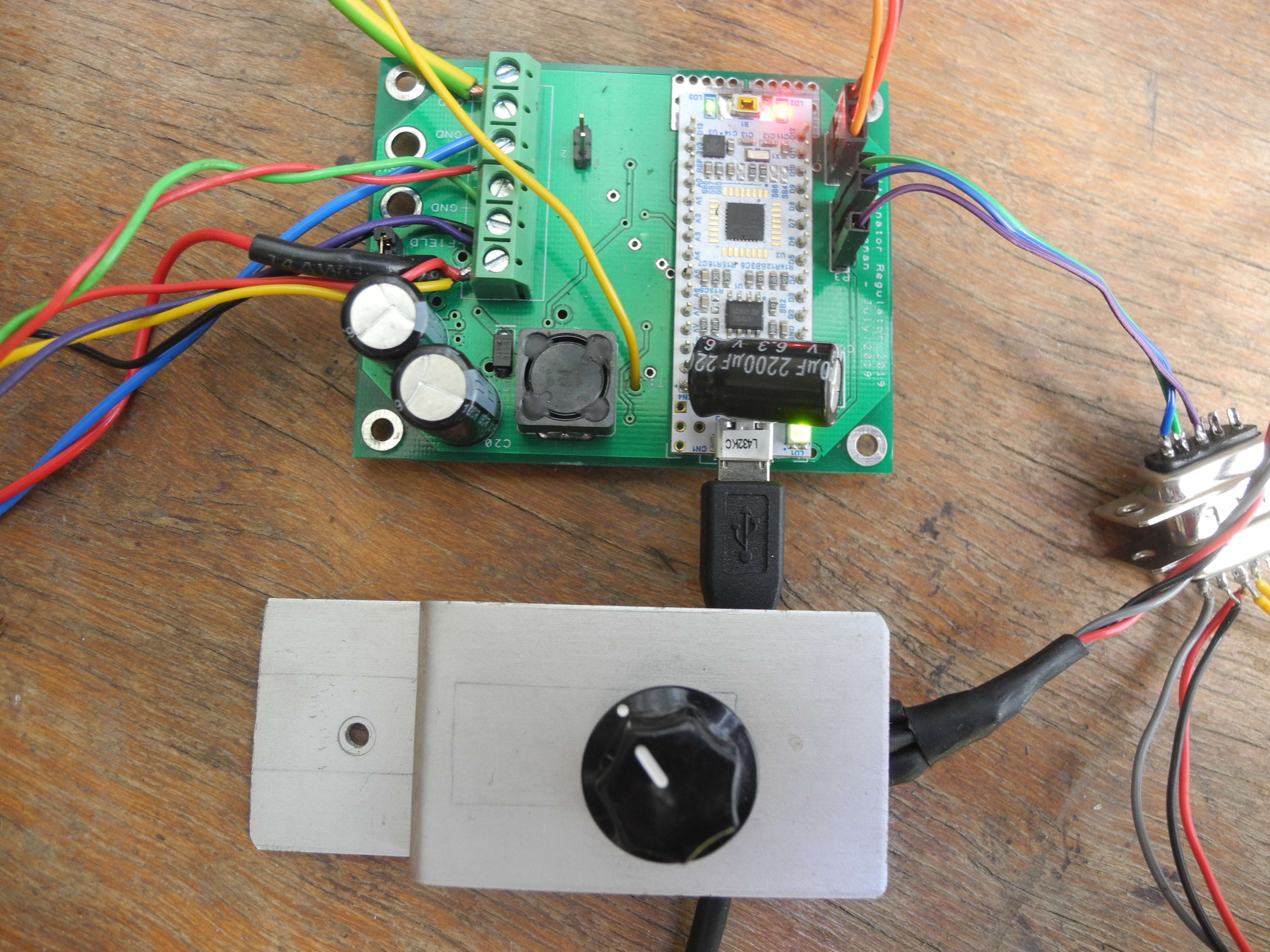
To provide the ‘intelligence’ needed, the smart regulator was designed around a 32 bit ARM Cortex M4 processor with built in floating point maths co-processor. For under a tenner you can buy one of these on a ‘ST Nucleo L432KC’ development board with USB connection for programming. This was selected. An EEPROM was designed in costing a few pence more. This is to contain any user setup options, including entries for the field current limit lookup table.
Making the most of the well resourced and powerful computer, peripherals designed in included an engine interface to measure engine speed, a servo for setting engine speed, voltmeters to measure driver’s control pot, alternator output and field voltages, an isolated ammeter capable of measuring output or battery current, a temperature sensor, a GPS module useful as a ground speedometer, a pressure sensor (possible use for vacuum brakes), with some spare logic inputs and outputs. An analogue PWM (pulse width modulator) subsystem regulates alternator output in the same way as the original regulator, except that this time we can choose the voltage. This also enables the computer to override and limit PWM duty ratio to lower output, to limit torque, so averting stalls. (Photo)
Software development was made easy by use of the free online development system from https://mbed.com. This will look quite familiar to users of Arduino, uses worldwide industry standard ‘C’ and ‘C++’ programming language, makes available a huge library of code modules for any device you might think of connecting, with too many useful features to list.
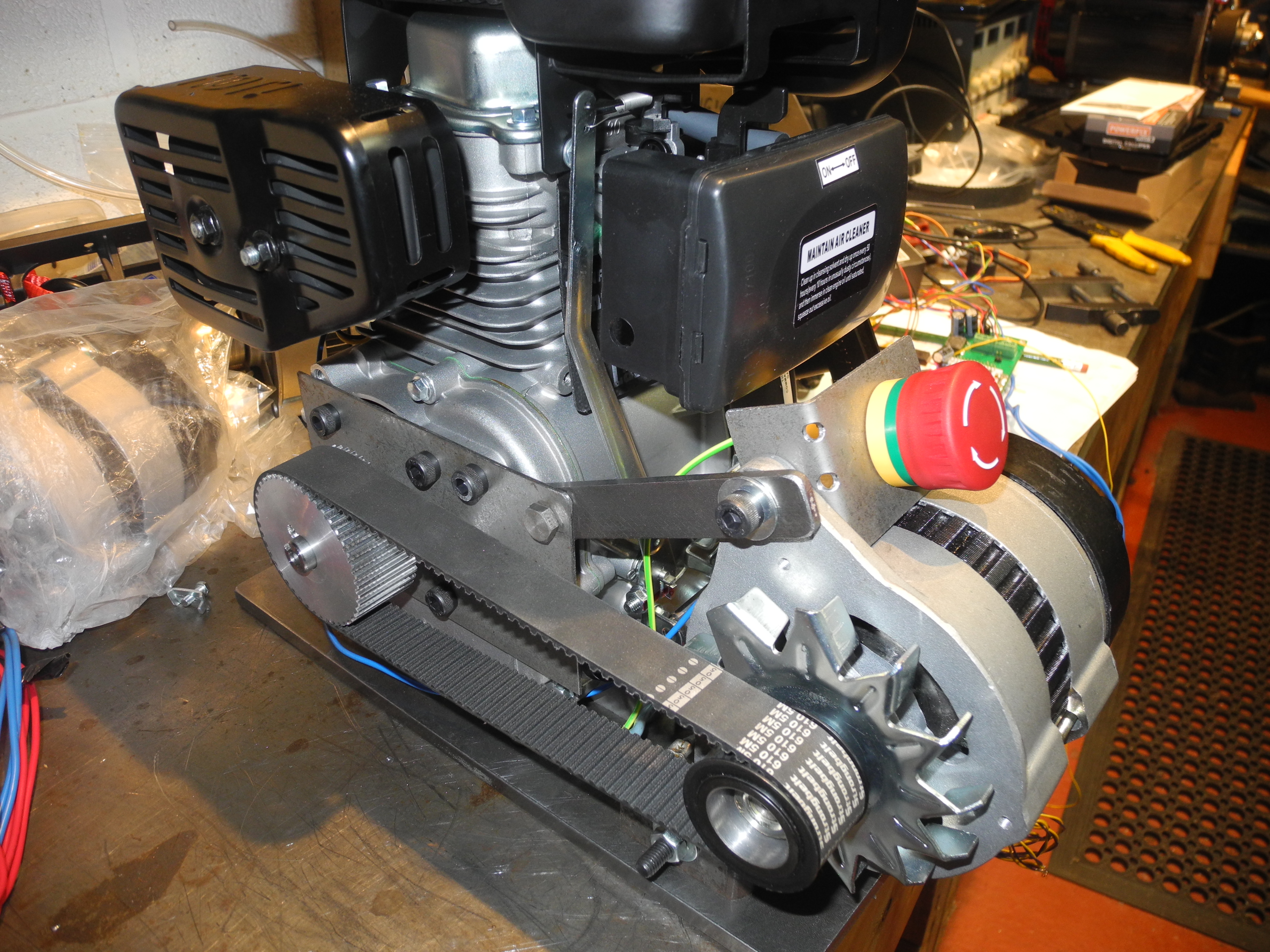
So much for the easy stuff. All the troubles and vexations start and end with the mechanics. To test the theory in practice a test rig was assembled using a Honda GX35 engine coupled inline to a Lucas ACR alternator. After running for probably less than an hour the drive coupling failed. A second attempt was made using a more substantial drive arrangement. This too failed in short time. Having by then deciding this high-revving 35cc engine was far too noisy to make it into any final loco design, a new start was made, a quieter engine was sourced, a Lifan 79cc, and a new test rig built, this time with engine and alternator coupled by drive belt instead of the failed inline configuration used with the Honda. Although more than twice the cylinder capacity, the new engine rated power is only 1.1kW compared to the 1.0kW rating of the Honda. So far this new rig has worked well, but although the alternator doesn’t care about rotational direction, the cooling fan does. On the failed rig rotation was in the ‘correct’ direction for the centrifugal fan to work pulling air through the alternator before casting it far and wide around the pulley. Now rotation is reversed and the fan will have little if any beneficial effect.
With the whole system together serious testing could begin. A dummy load was built consisting of a rack of ten, 60W 24V filament lamps, switchable in pairs. A number of ‘Operating Modes’ were coded including an ‘Auto Test’ mode. This runs the engine speed up in small steps measuring voltages, currents, speeds and other parameters at each stage, sending data via USB to a laptop for later spreadsheet analysis. Repeating auto test with different loads helped build a good picture of overall performance. Other modes for ‘fixed’ voltage using voltage change or current load to regulate engine speed are in there, but of more interest for a quick win with an interesting loco project, the ‘variable voltage’ scheme was paid greater attention. In this mode field current is held at zero for low engine speeds to avoid stalling. The driver’s pot is configured for power ‘off’ for the first 10% or so of range and controlling engine speed for higher settings. The smart regulator lookup table is set to give higher output at higher engine speeds. Turn the control up – get more power. It’s that simple.
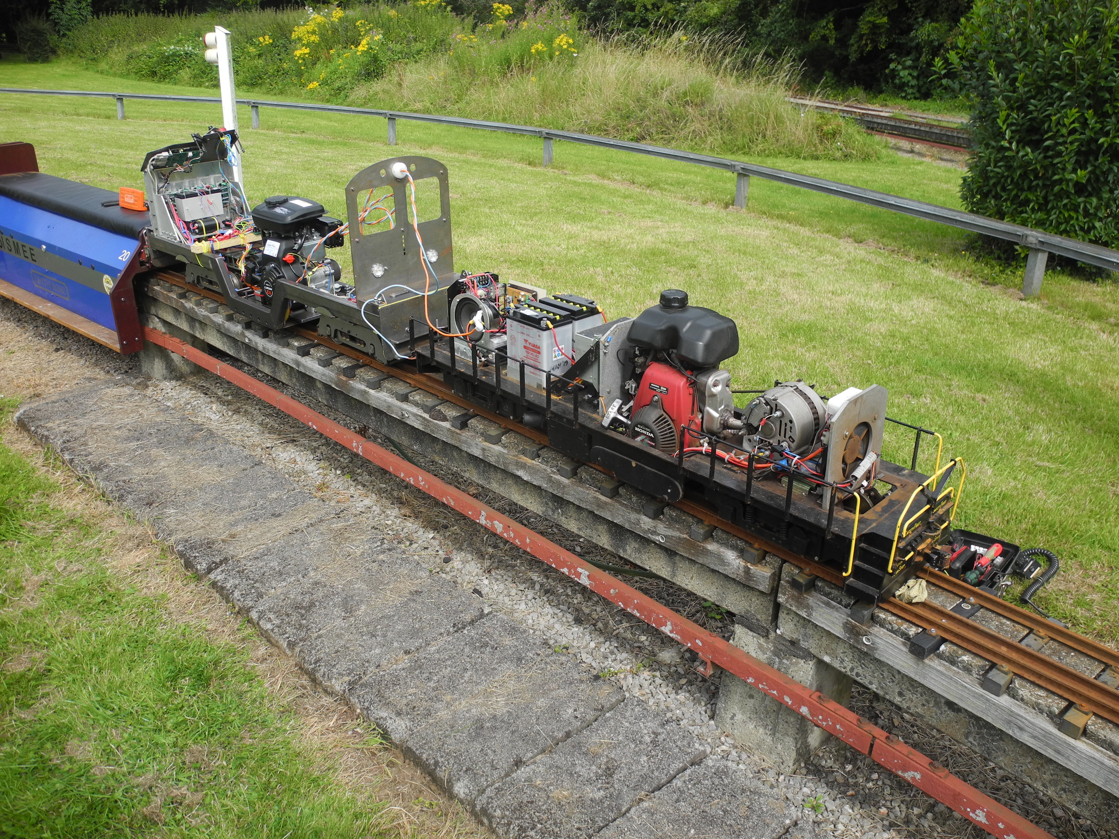
Preparing for the day out, the generator set was installed in the chassis of the Brushless Brute loco with the driver’s pot and an emergency engine stop switch temporarily clamped to the control panel. On arrival at Ashton this was connected and coupled up to Michigan (Photo), and a number of laps were completed. Having driven locos with batteries and mobility scooter controllers, I find it very dull setting the control to ‘6’ or whatever and then just completing laps with no need to think. The Low Cost Loco design needs to be driven, that is to say the power setting needs to be altered according to track gradients and conditions. More like driving a steam engine, less like a mobility scooter. A driver’s eye view of a lap can be seen in ''Low Cost Loco Test - Bristol - July 2020'' under the 'Vids' tab